Rockwell Automation Publication 750-PM001N-EN-P - February 2017 175
Drive Port 0 Parameters Chapter 3
APPLICATIONS
Torque Prove
1102 DI FloatMicroPsn
Digital Input Float Micro Position
Selects the digital input to be used for the float and micro position functions. Activates
the micro position function when selected and running. Activates float when stopping.
Default:
Min/Max:
0.00
0.00 / 159999.15
RW 32-bit
Integer
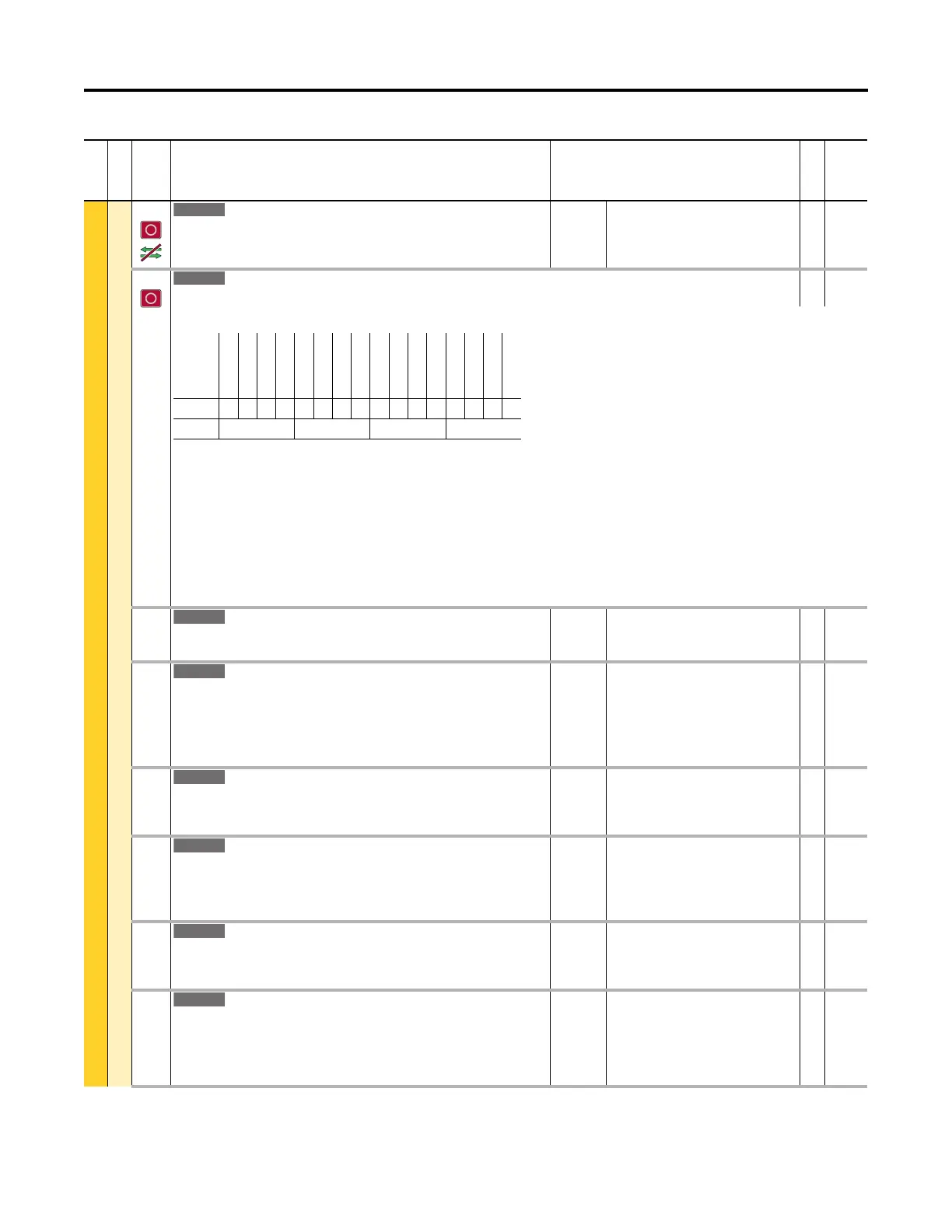
1103 Trq Prove Status
Torque Prove Status
RO 16-bit
Integer
Displays the status bits for TorqProve.
Bit 0 “EndLimitActv” – End travel limit active.
Bit 1 “DecelLmtActv” – Decel travel limit active.
Bit 2 “Micro Psn” – Micro position active.
Bit 3 “BrkSlip1 Alm” – Brake slip detected.
Bit 4 “Brake Set” – Brake signal set. For example set P10 [RO0 Sel] on the digital I/O module to Port 0, P1103 Bit 4 and set P6 [Dig Out Invert] Bit 0 = 1.
Bit 5 “LoadTestActv” – The test used to check the load for above base speed operation is active.
Bit 6 “RefLoadLmted” – The reference is limited due to the load test results.
Bit 7 “Encoderless” – Encoderless configure fault is active.
Bit 8 “BrakeRelease” – Inverted state of P1103 Bit 4.
1104 Trq Lmt SlewRate
Torque Limit Slew Rate
Sets the rate to ramp the torque limits to zero during brake proving.
Units:
Default:
Min/Max:
Secs
10.000
0.500 / 300.000
RW Real
1105 Speed Dev Band
Speed Deviation Band
The amount of allowable deviation between the commanded speed and the actual
speed (from a feedback device). When this value is exceeded for the amount of time in
P1106 [SpdBand Intgrtr], a fault will occur.
Units:
Default:
Min/Max:
Hz
RPM
P27 [Motor NP Hertz] x 0.0334
P28 [Motor NP RPM] x 0.0334
P27 x 0.0016 / P27 x 0.25
P28 x 0.0016 / P28 x 0.25
RW Real
1106 SpdBand Intgrtr
Speed Band Integrator
The amount of time for which the actual speed is allowed to deviate from P1105 [Speed
Dev Band] before a fault occurs.
Units:
Default:
Min/Max:
Secs
0.060
0.001 / 0.200
RW Real
1107 Brk Release Time
Brake Release Time
With an encoder, this parameter sets the time between the brake release command and
when the drive begins to accelerate.
Without an encoder, this parameter sets the time to release the brake after drive starts.
Units:
Default:
Min/Max:
Secs
0.100
0.000 / 10.000
RW Real
1108 Brk Set Time
Brake Set Time
Defines the amount of delay time between commanding the brake to be set and the
start of brake proving.
Units:
Default:
Min/Max:
Secs
0.100
0.000 / 10.000
RW Real
1109 Brk Alarm Travel
Brake Alarm Travel
Sets the number of motor shaft revolutions allowed during the brake slippage test. Drive
torque is reduced to check for brake slippage. When slippage occurs, the drive allows
this number of motor shaft revolutions before regaining control. Not used when P1100
[Trq Prove Cfg] Bit 1 “Encoderless” = 1 (enabled).
Default:
Min/Max:
1.00
0.00 / 1000.00
RW Real
File
Group
No. Display Name
Full Name
Description
Values
Read-Write
Data Type
Options
Reserved
Reserved
Reserved
Reserved
Reserved
Reserved
Reserved
BrakeRelease
Encoderless
RefLoadLmted
LoadTestActv
Brake Set
BrkSlip1 Alm
Micro Psn
DecelLmtActv
EndLimitActv
Default0000000000000000
Bit 1514131211109876543210
0 = Disabled
1 = Enabled
 Loading...


