Rockwell Automation Publication 750-PM001N-EN-P - February 2017 243
Embedded Feature and Option Module Parameters Chapter 5
11-Series I/O
Digital Outputs
6Dig Out Invert
Digital Output Invert
RW 16-bit
Integer
Inverts the selected digital output.
(1) Bit 1 = “Trans Out 0” for 11-Series I/O Module model 20-750-1133C-1R2T
= “Relay Out 1” for 11-Series I/O Module models 20-750-1132C-2R and 20-750-1132D-2R
(2) Bit 2 is only used by 11-Series I/O Module 20-750-1133C-1R2T
7 Dig Out Setpoint
Digital Output Setpoint
RW 16-bit
Integer
Controls Relay or Transistor Outputs when chosen as the source. Can be used to control outputs from a communication device using DataLinks.
(1) Bit 1 = “Trans Out 0” for 11-Series I/O Module model 20-750-1133C-1R2T
= “Relay Out 1” for 11-Series I/O Module models 20-750-1132C-2R and 20-750-1132D-2R
(2) Bit 2 is only used by 11-Series I/O Module 20-750-1133C-1R2T
10 RO0 Sel
Relay Output 0 Select
Selects the source that will energize the relay output.
Any status parameter bit can be used as an output source. For example P935 [Drive
Status 1] Bit 7 “Faulted.”
For Torque Proving set to Port 0, parameter 1103 Bit 4. Use N.O. for safety.
Default:
Min/Max:
0.00 (Disabled)
0.00 / 159999.15
RW 32-bit
Integer
11 RO0 Level Sel
Relay Output 0 Level Select
Selects the source of the level that will be compared.
Default:
Min/Max:
0 (Disabled)
0 / 159999
RW 32-bit
Integer
12 RO0 Level
Relay Output 0 Level
Sets the level compare value.
Default:
Min/Max:
0.0
–/+1000000.0
RW Real
13 RO0 Level CmpSts
Relay Output 0 Level Compare Status
RO 16-bit
Integer
Status of the level compare, and a possible source for a relay or transistor output. Relay Output n Select or Transistor Output n Select must have this selected to
energize the output. Can be used without a physical output as status information only.
Bit 0 “Less Than” – Level source is less than the level value.
Bit 1 “Grt Than Equ” – Level source is greater than or equal to the level value.
Bit 2 “Abs Less Than” – Absolute value of the level source is less than the absolute value of the level value.
Bit 3 “AbsGrtThanEq” – Absolute value of the level source is greater than or equal to the absolute value of the level value.
File
Group
No. Display Name
Full Name
Description
Values
Read-Write
Data Type
Options
Reserved
Reserved
Reserved
Reserved
Reserved
Reserved
Reserved
Reserved
Reserved
Reserved
Reserved
Reserved
Reserved
Trans Out 1
(2)
Trans Out 0
(1)
Relay Out 0
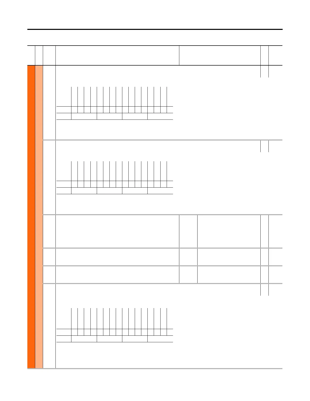
Default0000000000000000
Bit 1514131211109876543210
0 = Output Not Inverted
1 = Output Inverted
Options
Reserved
Reserved
Reserved
Reserved
Reserved
Reserved
Reserved
Reserved
Reserved
Reserved
Reserved
Reserved
Reserved
Trans Out 1
(2)
Trans Out 0
(1)
Relay Out 0
Default0000000000000000
Bit 1514131211109876543210
0 = Output De-energized
1 = Output Energized
Options
Reserved
Reserved
Reserved
Reserved
Reserved
Reserved
Reserved
Reserved
Reserved
Reserved
Reserved
Reserved
AbsGrtThanEq
Abs Less Than
Grt Than Equ
Less Than
Default0000000000000000
Bit 1514131211109876543210
0 = Condition False
1 = Condition True
 Loading...


