316 Rockwell Automation Publication 750-PM001N-EN-P - February 2017
Chapter 6 Troubleshooting
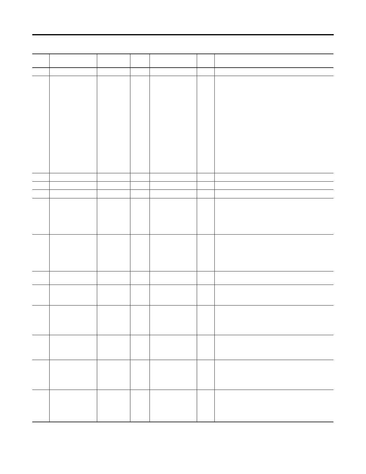
171 Adj Vltg Ref Alarm 1 Invalid adjustable-voltage reference selection conflict.
175 Travel Lim Cflct Non-Reset Fault Current
Limit
Stop
Travel limits are in conflict. Both the forward and reverse travel limits
indicate that they are simultaneously active.
If digital limits (hardware signals) are in use, ensure that the
following forward and reverse digital input pairs are not both off
simultaneously: fwd/rev decel travel limit digital inputs and fwd/rev
end stop travel limit digital inputs. The travel limit digital inputs are
meant to be connected to normally closed switch contacts, so the
digital input status reads an off (0 = False) bit status when the
machine is on limit and the switch contact opens. A possible cause for
this condition is loss of common power to both the forward and
reverse travel limit switches.
If software travel limits are in use, check the state of the fwd/rev
travel limit bits in P1101 [Trq Prove Setup]. These bits read an on (1 =
Enabled) bit status when the machine is on limit. Bit 2 “Decel Fwd”
and Bit 4 “Decel Rev” should not be on simultaneously. Similarly, Bit 3
“End Stop Fwd” and Bit 5 “End Stop Rev” should not be on
simultaneously.
177 Profiling Active Alarm 1 The Profile/Indexer is active.
178 Homing Active Alarm 1 The Homing function is active.
179 Home Not Set Alarm 1 The Home position was not set before profile operation.
181 Fwd End Limit Resettable Fault Current
Limit
Stop
The selected digital input for one of the end limit switches, P196 [DI
Fwd End Limit] or P198 [DI Rev End Limit], has detected a falling edge
and P313 [Actv SpTqPs Mode] is not set to 1 “Speed Reg.”
If digital limits (hardware signals) are in use, ensure that the digital
inputs are connected to normally closed contacts. When the end limit
is reached the contacts open.
182 Rev End Limit Resettable Fault Current
Limit
Stop
The selected digital input for one of the end limit switches, P196 [DI
Fwd End Limit] or P198 [DI Rev End Limit], has detected a falling edge
and P313 [Actv SpTqPs Mode] is not set to 1 “Speed Reg.”
If digital limits (hardware signals) are in use, ensure that the digital
inputs are connected to normally closed contacts. When the end limit
is reached the contacts open.
185 Freq Conflict Alarm 2 Indicates that the values of P520 [Max Fwd Speed] and P521 [Max
Rev Speed] are in conflict with the value of P63 [Break Frequency].
186 VHz Neg Slope Alarm 2 Indicates that the V/Hz curve segment resulted in a negative V/Hz
slope.
See P60 [Start Acc Boost] through P63 [Break Frequency].
187 VHz Boost Limit Alarm 2 Indication that one of the two following conditions exists.
• P60 [Start/Acc Boost] and P61 [Run Boost] are greater than P25
[Motor NP Volts] x 0.25 when P65 [VHz Curve] = 0 “Custom V/Hz.”
• P61 [Run Boost] is greater than P25 [Motor NP Volts] x 0.25 when
P65 [VHz Curve] = 1 “Fan/Pump.”
190 PM FV Pri Fdbk Alarm 2 Indicates a control mode and primary-feedback device configuration
error. P35 [Motor Ctrl Mode] is set to the permanent magnet flux
vector “PM FV” control mode, P125 [Pri Vel Fdbk Sel] is set to P137
[Open Loop Fdbk] (port 0).
191 PM FV Alt Fdbk Alarm 2 Indicates a control mode and alternate-feedback device configuration
error. P35 [Motor Ctrl Mode] is set to the permanent magnet flux
vector “PM FV” control mode, P635 [Spd Options Ctrl] is set to bit 7
“Auto Tach SW,” P128 [Alt Vel Fdbk Sel] is set to P137 [Open Loop
Fdbk] (port 0).
192 Fwd Spd Lim Cfg Alarm 2 The forward speed reference is out of range.
Verify the settings of P38 [PWM Frequency] and P520 [Max Fwd
Speed]. Lower carrier frequencies reduce the output frequency range.
Verify that P522 [Min Fwd Speed] is less than or equal to P520 [Max
Fwd Speed].
Event
No.
Fault/Alarm Text Type Fault
Action
Configuration
Parameter
Auto
Reset
Description/Action(s)
 Loading...


