Rockwell Automation Publication 750-PM001N-EN-P - February 2017 319
Troubleshooting Chapter 6
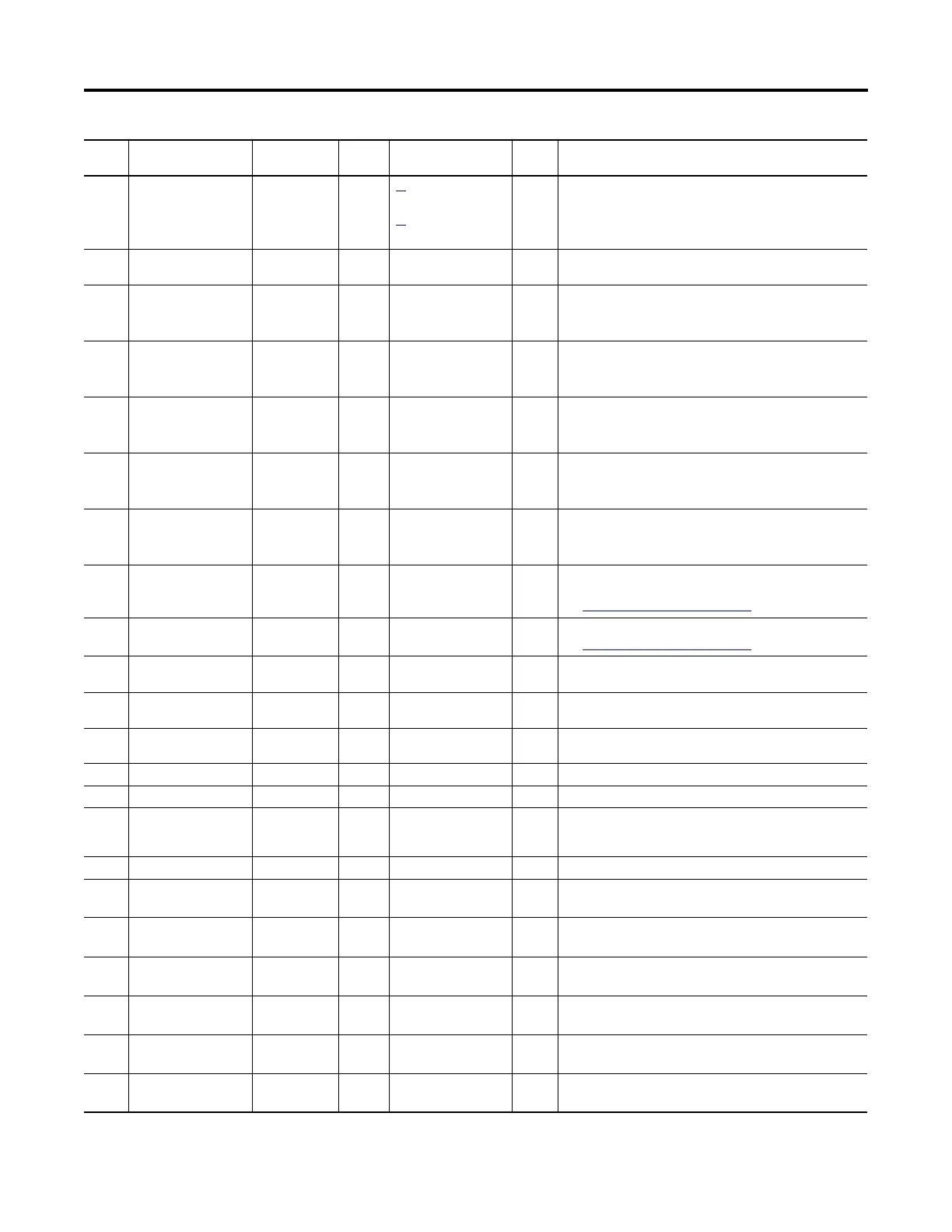
322 N-1 Operation Alarm 1 20
(Port 10)
[Recfg Acknowledg]
21
(Port 10)
[Effctv I Rating]
Drive is operating with fewer inverters than the original parallel
configuration.
324 DC Bus Mismatch Non-Reset Fault Coast There is a bus voltage imbalance between parallel inverters that is
greater than 50V DC.
327
328
329
HS Temp Imbal U
HS Temp Imbal V
HS Temp Imbal W
Alarm 1 There is a heatsink temperature imbalance between parallel inverters
in the phase indicated that is greater than 11.5 °C (52.7 °F).
331
332
333
I1 Comm Loss
I2 Comm Loss
I3 Comm Loss
Resettable Fault Coast A communications fault has occurred between the main control board
and the power layer interface board on inverter n.
341
342
343
C1 Comm Loss
C2 Comm Loss
C3 Comm Loss
Resettable Fault Coast A communications fault has occurred between the main control board
and the converter gate board on converter n.
351
352
353
In Cur Share L1
In Cur Share L2
In Cur Share L3
Alarm 1 There is an input current sharing imbalance between parallel
converters in the AC line indicated that is greater than 15 % of the
converter rated current.
357
358
359
In Vlt Imbal L12
In Vlt Imbal L23
In Vlt Imbal L31
Alarm 1 There is an input line voltage imbalance between parallel converters
in the AC lines indicated that is greater than 5 % of the converter rated
voltage.
360 N-1 See Manual Resettable Fault Coast The number of active inverters has been reduced from the original
parallel configuration.
See N-1 and Re-Rate Functions
on page 337.
361 Rerate See Manual Resettable Fault Coast The drive rating has changed from the original parallel configuration.
See N-1 and Re-Rate Functions on page 337.
362 Cnv/Inv Mismatch Alarm 2 There is a voltage class mismatch between the installed parallel
inverters and converters.
363 CBP/Inv Mismatch Alarm 2 There is a voltage class mismatch between the installed parallel
inverters and common DC bus precharge units.
364 CBP Num Mismatch Alarm 2 The number of active inverters and active common DC bus precharge
units does not match.
365 Zero Cnv/Prechrg Alarm 2 No converter or common DC bus precharge unit exists.
366 Cnv Num Mismatch Alarm 2 The number of active inverters and active converters does not match.
371
372
P1 Comm Loss
P2 Comm Loss
Resettable Fault Coast A communications fault has occurred between the main control board
and the DC precharge control board on the common DC bus precharge
unit n.
380 PWM FPGA Overrun Alarm 1 The time limit on the PWM write to the FPGA was exceeded.
900 900 Automatic Drive
Reset
Coast Critical input exception.
Contact technical support.
901 Machine Check Automatic Drive
Reset
Coast Internal error.
Replace the main control board.
902 Data Storage Error Automatic Drive
Reset
Coast Cache memory corrupt.
Replace the main control board.
903 Instruction Storage Error Automatic Drive
Reset
Coast Cache memory corrupt.
Replace the main control board.
905 Alignment Error Automatic Drive
Reset
Coast Pointer is pointing to a non-boundary member.
Obtain test points and check grounding.
906 Program Error Automatic Drive
Reset
Coast Bad memory read.
Check grounding or replace the main control board.
Event
No.
Fault/Alarm Text Type Fault
Action
Configuration
Parameter
Auto
Reset
Description/Action(s)
 Loading...


