504 Rockwell Automation Publication 750-PM001N-EN-P - February 2017
Appendix F Integrated Motion on EtherNet/IP Application
The 20-750-DENC-1 and 20-750-UFB-1 modules contain two “hardware
feedback channels”, which means up to two encoders can be connected to each
module. The 20-750-ENC-1 only contains one hardware feedback channel.
An Integrated Motion on EtherNet/IP Axis can have up to two feedback devices
that are associated with it. When two devices are in use, they are defined as the
“Motor Feedback Device” and the “Load Feedback Device.” These two devices
are also referred to as “Integrated Motion on EtherNet/IP Feedback 1” and
“Integrated Motion on EtherNet/IP Feedback 2,” respectively.
Each Integrated Motion on EtherNet/IP feedback device has an associated
Integrated Motion on EtherNet/IP feedback type. The feedback type describes
the type of encoder that can be used as that feedback device.
When configuring a drive using RSLogix 5000 and Integrated Motion on
EtherNet/IP, the Associated Axes page of the drive Module Properties dialog is
used to associate each feedback device with a feedback hardware channel on the
drive.
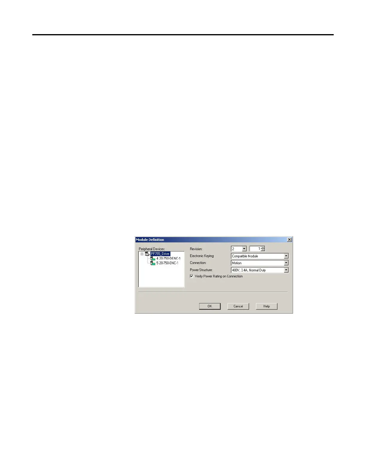
Before using the Associated Axes page, each feedback module present in the drive
must be defined on the Module Definition dialog box. The Module Definition
dialog box is accessed from the General tab of the Module Properties dialog box
for the drive.
After each feedback module has been defined, a drive hardware feedback channel
must be selected for each feedback device. A list defines each available channel by
the control-pod port number of the feedback module and the channel within
that port. A sequential alphabetic character is used to identify each available
feedback channel for a module. For example, if a feedback module contains two
channels, they are identified as “Channel A” and “Channel B.”
The correct wiring for an encoder in this system depends on three things:
• The type of feedback module
• The type of encoder
• Which hardware feedback channel is used to connect the encoder (A or B)
If there is only one way to wire an encoder to a feedback module, then either
hardware Channel A or Channel B can be selected for the feedback module.
 Loading...


