52 Rockwell Automation Publication 750-PM001N-EN-P - February 2017
Chapter 3 Drive Port 0 Parameters
MOTOR CONTROL
Mtr Ctrl Options
40 Mtr Options Cfg
Motor Options Configuration
RW 32-bit
Integer
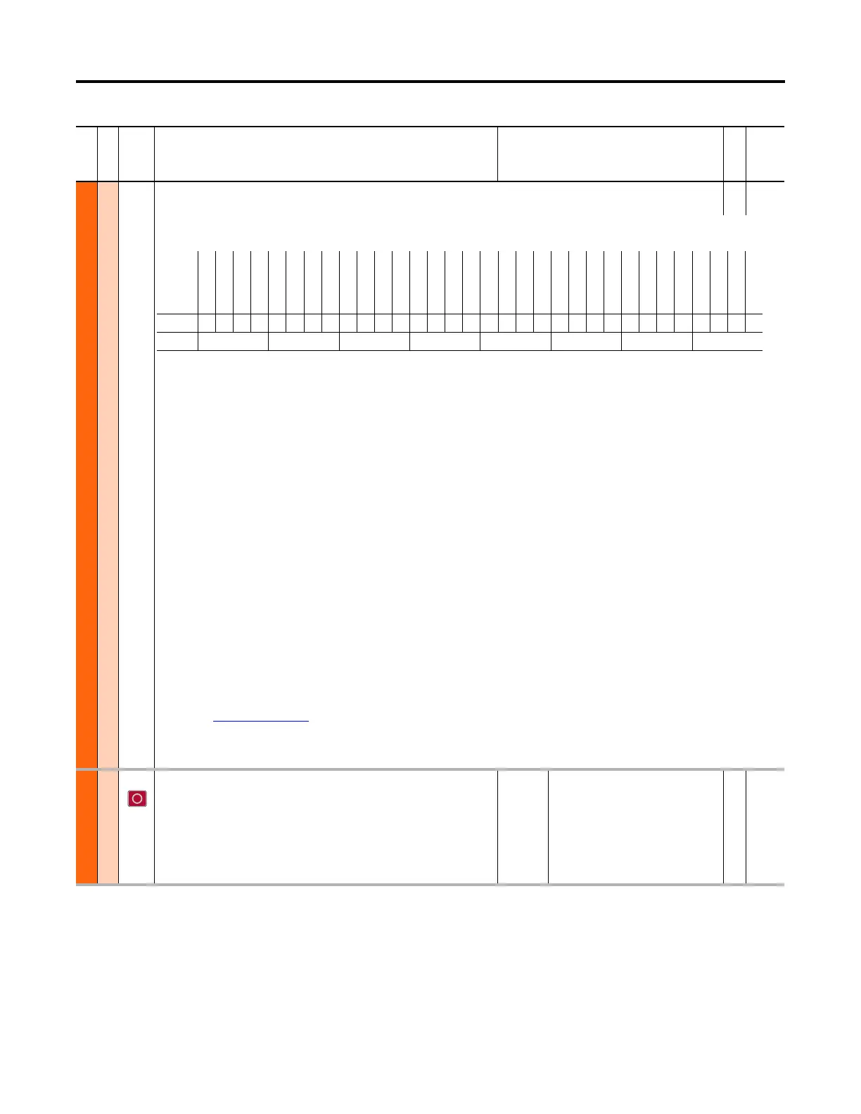
Configuration of motor control-related functions. For motors above 200 Hz, a carrier frequency of 8 kHz or higher is recommended. Consider drive derate and motor
lead distance restrictions.
Bit 0 “Zero TrqStop” – Configures stopped condition when in torque mode. 0 = wait for zero speed before shutting off drive output, 1 = wait for zero torque before
shutting off drive output.
Bit 1 “Trq ModeStop” – Configures stopping behavior when in torque mode. 0 = remain in torque mode, 1 = switch to speed mode
Bit 2 “Trq ModeJog” – Configures jogging behavior when in torque mode. 0 = remain in torque mode, 1 = switch to speed mode
Bit 3 “EnclsTrqProv” – Enables encoderless mode when using the torque prove function. 0 = Disabled, 1 = Enabled. Bits 0 and 1 of P1100 [Trq Prove Cfg] must also
be set to use this mode.
Bit 4 “Mtr Lead Rev” – Reverses the phase rotation of the applied voltage, effectively reversing the motor leads. 0 = Not Reversed, 1 = Reversed
Bit 5 “Reflect Wave” – Enables reflected wave voltage protection for long motor cables. 0 = Disabled, 1 = Enabled
Bit 6 “RS Adaption” – Adapts for changes in motor stator resistance due to motor temperature. Active only in FV motor control mode with feedback. 0 = Disabled, 1
= Enabled
Bit 7 “PWM Type Sel” – Configures 3 Phase / 2 Phase switching of the power devices. 0 = 3 Phase modulation with auto switchover to 2 phase modulation. 1 = Full
time 3 phase modulation (no switchover)
Bit 8 “AsyncPWMLock” – Configures Synchronous / Asynchronous switching of the power devices. 0 = Automatically changes between synchronous and
asynchronous. 1 = Asynchronous switching only.
Bit 9 “PWM FreqLock” – Configures switching frequency of the power devices while in FV motor control mode without feedback. 0 = switching frequency
automatically reduces to 2 kHz at low speeds (best performance), 1 = switching frequency does not reduce (setting used when switching frequency reduction is
undesirable)
Bit 10 “DB WhileStop” – Enables operation of the dynamic brake transistor while the drive is stopped. 0 = Disabled, 1 = Enabled
Bit 11 “Elect Stab” – Enables stability control for Sensorless Vector and V/Hz motor control modes. 0 = Disabled, 1 = Enabled
Bit 12 “Xsistor Diag” – Enables power transistor diagnostic test at each start command. Recommended to set to Disabled if an output filter is installed with the
drive. Refer to publication PFLEX-AT002
for additional information. 0 = Disabled, 1 = Enabled
Bit 13 “Common Mode” – Enables the common mode reduction feature. See Parameter 41, Common Mode Type, for common mode type selection.
Bit 15 “Jerk Select” – Limits the rate of change to the velocity reference for improved current limiting. This setting applies only to Sensorless Vector and V/Hz motor
control modes. 0 = Disabled (0.0 second ramp time achievable), 1 = Enabled (0.0 second ramp time prevented)
41 Common Mode Type
Common Mode Type
CMV (0) – Reduces common mode voltage that degrades motor bearings and corrupts
signals in control systems. It produces high DC bus ripple and reduces DC bus capacitor
life.
CMI (1) – Reduces common mode current within the drive that helps reduce the stress
on the power components when the jumpers are disconnected on a solidly grounded
network.
Default:
Options:
0 – CMV
0 – CMV
1 – CMI
RW 32-bit
Integer
File
Group
No. Display Name
Full Name
Description
Values
Read-Write
Data Type
Options
Reserved
Reserved
Reserved
Reserved
Reserved
Reserved
Reserved
Reserved
Reserved
Reserved
Reserved
Reserved
Reserved
Reserved
Reserved
Reserved
Jerk Select
Not Used
Common Mode
Xsistor Diag
(1)
(1) 753 drive default is 1 = Enabled.
755 drive default is 0 = Disabled.
Elect Stab
DB WhileStop
PWM FreqLock
AsyncPWMLock
PWM Type Sel
RS Adaption
Reflect Wave
Mtr Lead Rev
EnclsTrqProv
(2)
(2) 755 drives only.
Trq ModeJog
Trq ModeStop
Zero TrqStop
Default00000000000000001001100011100111
Bit 323029282726252423222120191817161514131211109876543210
 Loading...


