Digital Outputs 2-65
chosen “driver” is Temperature, the drive assumes that the entered value
for the limit [Dig Outx Level] is degrees C. No units will be reported to
LCD HIM users, offline tools, devices communicating over a network,
PLC’s, etc.
The online and offline limits for the digital output threshold parameters
will be the minimum and maximum threshold value required for any
output condition.
If the user changes the currently selected output condition for a digital
output, then the implied units of the corresponding threshold parameter
will change with it, although the value of the parameter itself will not.
For example, if the output is set for “At Current” and the threshold for
100, drive current over 100% will activate the relay. If the user changes
the output to “At Temp”, the relay will deactivate (even if current >
100%) because the drive is cooler than 100 degrees C.
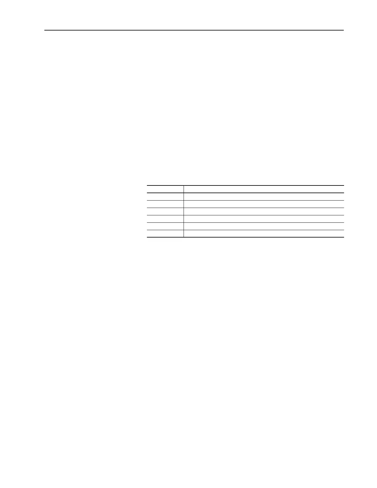
The following values can be annunciated
3. The relay changes state because a Digital Input link has been established
and the Input is closed.
An Output can be “linked” directly to an Digital Input so that the output
“tracks” the input. When the input is closed, the Output will be
energized, and when the input is open, the output will be de-energized.
This “tracking will occur if two conditions exist:
– The Input is configured for any choice other than “Unused”
– The Output is configured for the appropriate “Input x Link”
Note that the output will continue to track or be controlled by the state of
the input, even if the input has been assigned a function (i.e. Start, Jog)
Output Time Delay
Each digital output has two user-controlled timers associated with it.
One timer (the ON timer) defines the delay time between a FALSE to TRUE
transition (condition appears) on the output condition and the corresponding
change in state of the digital output.
The second timer (the OFF timer) defines the delay time between a TRUE
to FALSE transition (condition disappears) on the output condition and the
corresponding change in the state of the digital output.
Value Description
At Freq The drive output frequency equals or exceeds the programmed Limit
At Current The drive total output current exceeds the programmed Limit
At Torque The drive output torque current component exceeds the programmed Limit
At Temp The drive operating temperature exceeds the programmed Limit
At Bus Volts The drive bus voltage exceeds the programmed Limit
At PI Error The drive Process PI Loop error exceeds the programmed Limit

 Loading...


