2-66 Digital Outputs
The user can disable either timer by setting the corresponding delay time to
0.
Important:Note that whether a particular type of transition (FALSE to
TRUE or TRUE TO FALSE) on an output condition results in
an energized or de-energized output depends on the output
condition.
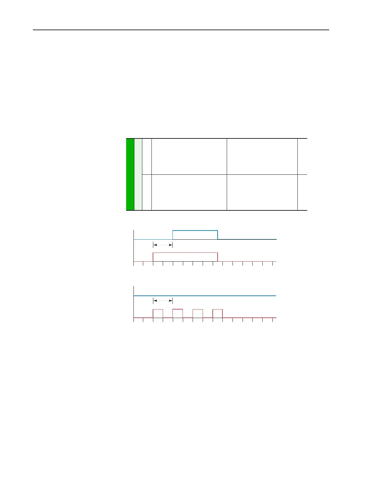
If a transition on an output condition occurs and starts a timer, and the
output condition goes back to its original state before the timer runs out,
then the timer will be aborted and the corresponding digital output will not
change state.
382
386
[Dig Out1 OnTime]
[Dig Out2 OnTime]
Sets the “ON Delay” time for the digital
outputs. This is the time between the
occurrence of a condition and activation
of the relay.
Default:
Min/Max:
Display:
0.0 Secs
0.0 Secs
0.0/600.0 Secs
0.1 Secs
380
383
387
[Dig Out1 OffTime]
[Dig Out2 OffTime]
Sets the “OFF Delay” time for the digital
outputs. This is the time between the
disappearance of a condition and
de-activation of the relay.
Default:
Min/Max:
Display:
0.0 Secs
0.0 Secs
0.0/600.0 Secs
0.1 Secs
380
CR1 On Delay = 2 Seconds
CR1 On Delay = 2 Seconds
0510
0
5
10
Relay Activates
Current Limit Occurs
Relay Does Not Activate
Cyclic Current Limit
(every other second)

 Loading...


