1-2 Installation/Wiring
PowerFlex 40 Adjustable Frequency AC Drive FRN 1.xx - 7.xx User Manual
Publication 22B-UM001I-EN-E
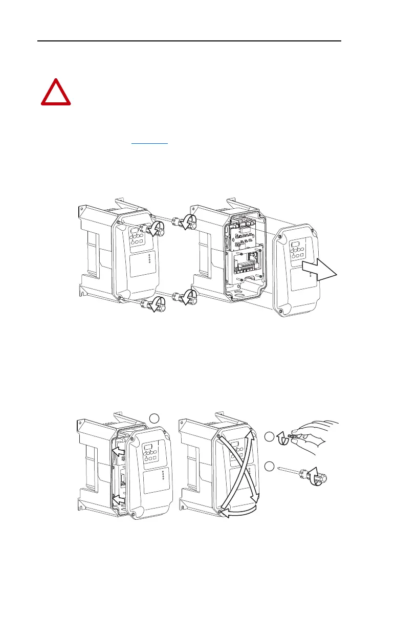
IP66, NEMA/UL Type 4X
1. Loosen the four captive cover screws.
2. Pull cover straight off chassis.
IP66, NEMA/UL Type 4X Cover Installation
1. Squarely align the cover on the chassis.
2. Lightly tighten the four captive cover screws.
3. Torque the cover screws using an alternating pattern.
ATTENTION: To avoid an electric shock hazard, ensure isolation of
mains supply from line inputs [R, S, T (L1, L2, L3)] and wait three
minutes for capacitors to discharge before removing the external cover.
Once the cover is removed, verify that the voltage on the bus capacitors
has discharged before performing any work on the drive. Measure the
DC bus voltage at the DC– and DC+ terminals on the Power Terminal
Block (refer to page 1-13
for Power Terminal descriptions). The voltage
must be zero.
1
3
4
2
0.8 ±0.2 N-m
(7.0 ±2.0 lb.-in.)
2
1
3
22B-UM001.book Page 2 Tuesday, May 30, 2017 5:22 PM

 Loading...


