Installation/Wiring 1-5
PowerFlex 40 Adjustable Frequency AC Drive FRN 1.xx - 7.xx User Manual
Publication 22B-UM001I-EN-E
Ungrounded Distribution Systems
Disconnecting MOVs
To prevent drive damage, the MOVs connected to ground shall be
disconnected if the drive is installed on an ungrounded distribution
system where the line-to-ground voltages on any phase could exceed
125% of the nominal line-to-line voltage. To disconnect these devices,
remove the jumper shown in the Figures 1.1
and 1.2.
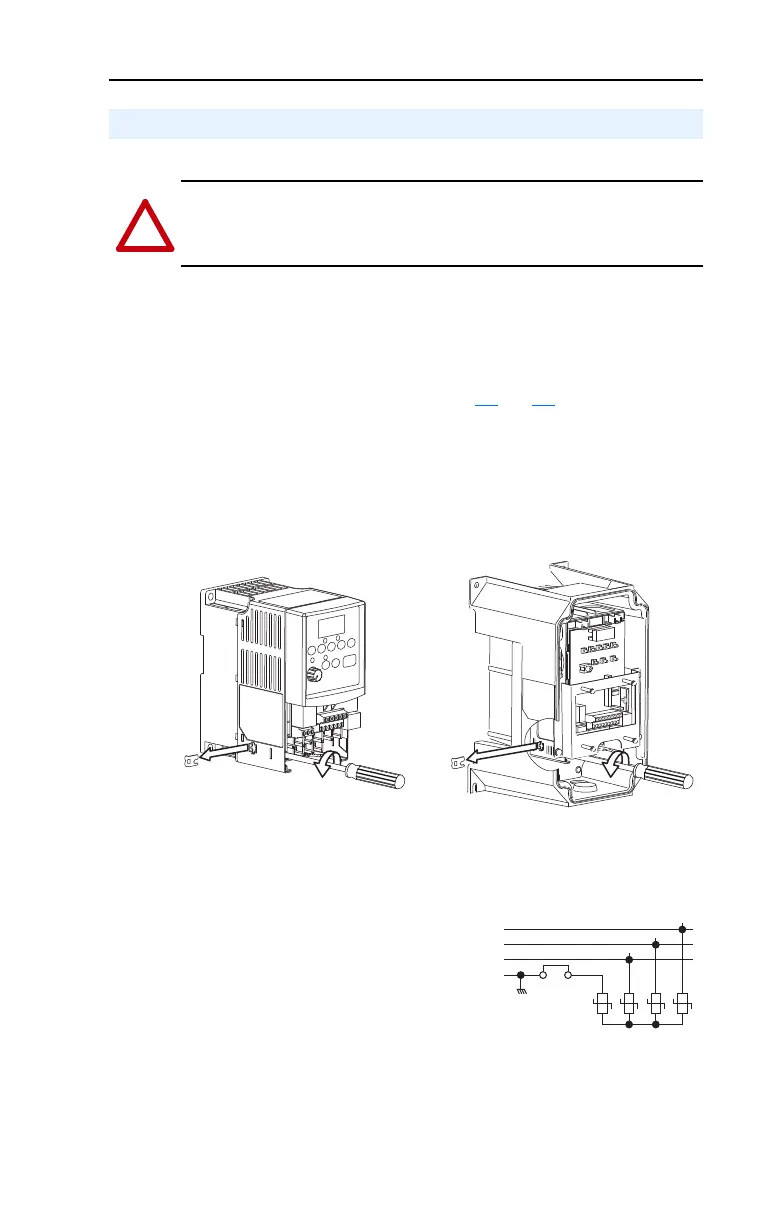
1. Turn the screw counterclockwise to loosen.
2. Pull the jumper completely out of the drive chassis.
3. Tighten the screw to keep it in place.
Figure 1.1 Jumper Location (Typical)
Figure 1.2 Phase to Ground MOV Removal
AC Supply Source Considerations
ATTENTION: PowerFlex 40 drives contain protective MOVs that are
referenced to ground. These devices must be disconnected if the drive is
installed on an ungrounded or resistive grounded distribution system.
Important: Tighten screw after jumper removal.
IP66, NEMA/UL Type 4XIP20, NEMA/UL Type Open
R/L1
S/L2
T/L3
123
4
Three-Phase
AC Input
Jumper
22B-UM001.book Page 5 Tuesday, May 30, 2017 5:22 PM

 Loading...


