Installation/Wiring 1-19
PowerFlex 40 Adjustable Frequency AC Drive FRN 1.xx - 7.xx User Manual
Publication 22B-UM001I-EN-E
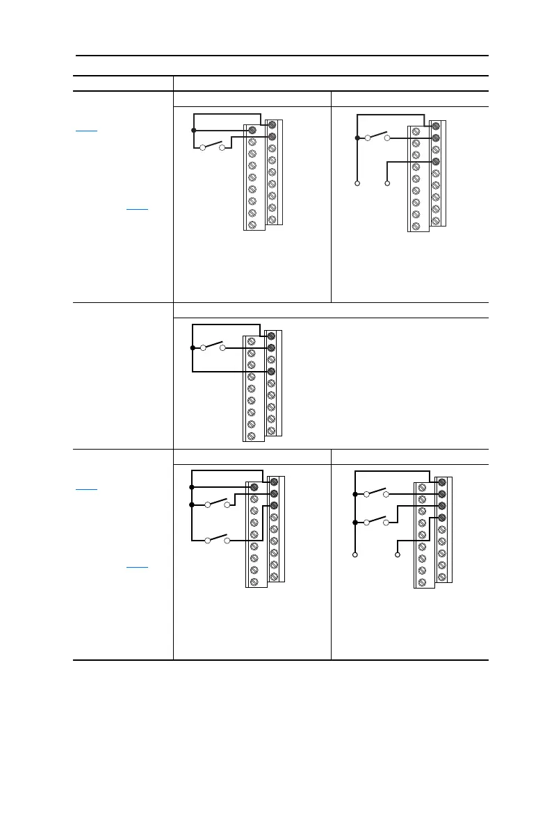
2 Wire SRC Control -
Non-Reversing
P036
[Start Source] =
2, 3 or 4
Input must be active for
the drive to run. When
input is opened, the
drive will stop as
specified by P037
[Stop Mode].
If desired, a User
Supplied 24V DC
power source can be
used. Refer to the
“External Supply
(SRC)” example.
Internal Supply (SRC) External Supply (SRC)
2 Wire SNK Control -
Non-Reversing
Internal Supply (SNK)
2 Wire SRC Control -
Run FWD/Run REV
P036
[Start Source] =
2, 3 or 4
Input must be active for
the drive to run. When
input is opened, the
drive will stop as
specified by P037
[Stop Mode].
If both Run Forward
and Run Reverse
inputs are closed at the
same time, an
undetermined state
could occur.
Internal Supply (SRC) External Supply (SRC)
Input/Output Connection Example
+24V Common
01
02
04
Stop-Run
Each digital input draws 6 mA.
11
01
02
03
Stop-Run
Forward
Stop-Run
Reverse
Common
01
02
03
04
Stop-Run
Forward
Stop-Run
Reverse
+24V
Each digital input draws 6 mA.
22B-UM001.book Page 19 Tuesday, May 30, 2017 5:22 PM

 Loading...


