Installation/Wiring 1-21
PowerFlex 40 Adjustable Frequency AC Drive FRN 1.xx - 7.xx User Manual
Publication 22B-UM001I-EN-E
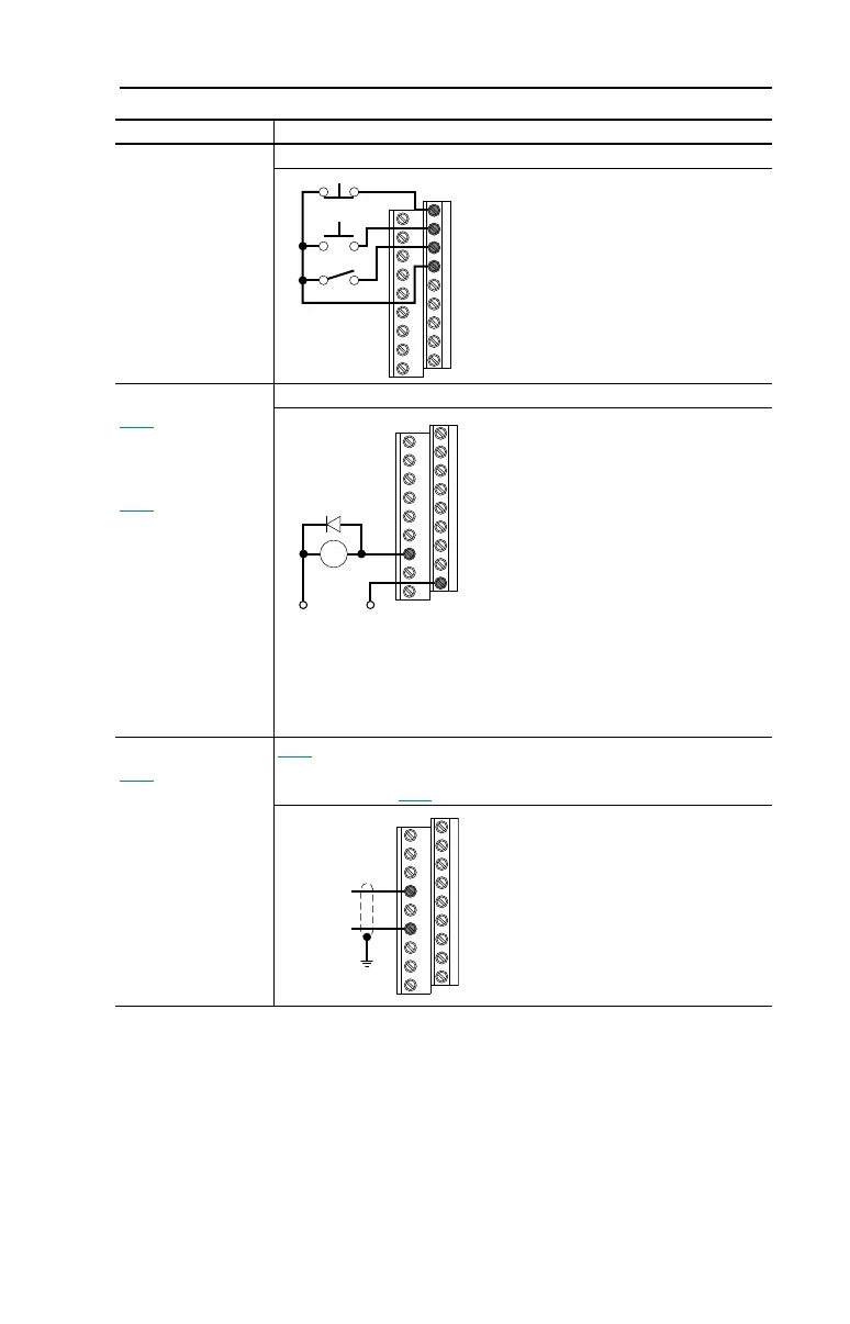
3 Wire SNK Control -
Reversing
Internal Supply (SNK)
Opto Output (1 & 2)
A058
[Opto Out1 Sel]
determines
Opto-Output 1 (I/O
Terminal 17) operation.
A061
[Opto Out2 Sel]
determines
Opto-Output 2 (I/O
Terminal 18) operation.
When using
Opto-Output with an
inductive load such as
a relay, install a
recovery diode parallel
to the relay as shown,
to prevent damage to
the output.
Opto-Output 1
Analog Output
A065
[Analog Out Sel]
determines analog
output type and drive
conditions.
0-10V,
1k ohm minimum
0-20mA/4-20mA,
525 ohm maximum
A065
[Analog Out Sel] = 0 through 14
The Analog Output Select DIP Switch must be set to match the analog output
signal mode set in A065
[Analog Out Sel].
Input/Output Connection Example
Stop
Start
Direction
01
02
03
04
Each Opto-Output is rated
30V DC 50 mA (Non-inductive).
22B-UM001.book Page 21 Tuesday, May 30, 2017 5:22 PM

 Loading...


