Rockwell Automation Publication 1783-UM007G-EN-P - February 2017 117
Install Stratix 5410 Switches Chapter 4
3. Open the cover.
The terminal screws labels are on the power-input terminal cover.
4. To connect from the power-input terminal to the power source, use
twisted-pair copper wire (12-AWG to 18-AWG).
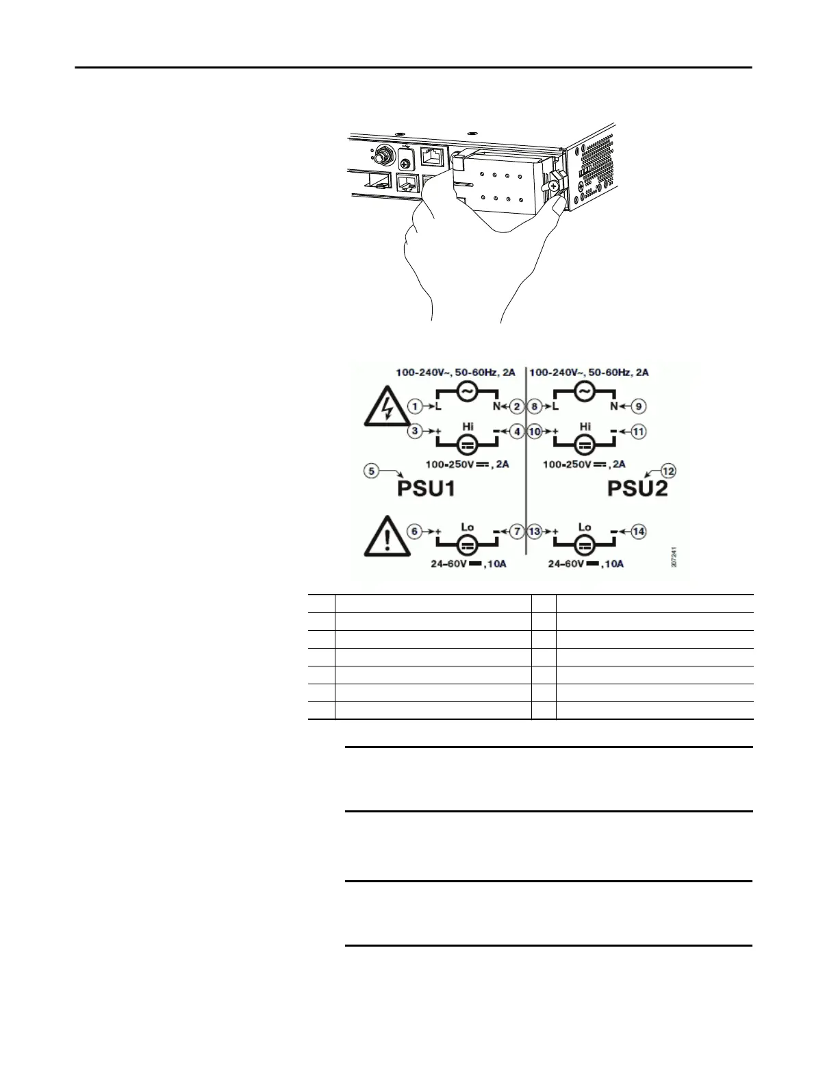
1 Line connection for high-voltage AC (PSU1) 8 Line connection for high-voltage AC (for PSU2)
2 Neutral connection for high-voltage AC (PSU1) 9 Neutral connection for high-voltage AC (PSU2)
3 Positive connection for high-voltage DC (PSU1) 10 Positive connection for high-voltage DC (PSU2)
4 Negative connection for high-voltage DC (PSU1) 11 Negative connection for high-voltage DC (PSU2)
5 PSU1 (power-supply module 1) 12 PSU2 (power-supply module 2)
6 Positive connection for low-voltage DC (PSU1) 13 Positive connection for low-voltage DC (PSU2)
7 Negative connection for low-voltage DC (PSU1) 14 Negative connection for low-voltage DC (PSU2)
IMPORTANT The power supply module 1 connection is labeled PSU1, and the
power supply module 2 connection is labeled PSU2. Make sure that
you connect the wires to the correct terminal screws.
IMPORTANT Use 12 AWG (minimum) for the low-voltage DC power supply
module. Use 16 AWG (minimum) for the high-voltage AC or DC power
supply module.
32559-M
Con
s
ole
28
ANA.TimeCode
TOD
IN
O
U

 Loading...


