EasyManuals Logo

Allen-Bradley Studio 5000 Logix Emulate User Manual

Allen-Bradley Studio 5000 Logix Emulate
676 pages
To Next Page IconTo Next Page
To Previous Page IconTo Previous Page
Page #365 background imageLoading...
Page #365 background image
Chapter 6
Rockwell Automation Publication MOTION-RM002H-EN-P-February 2018 365
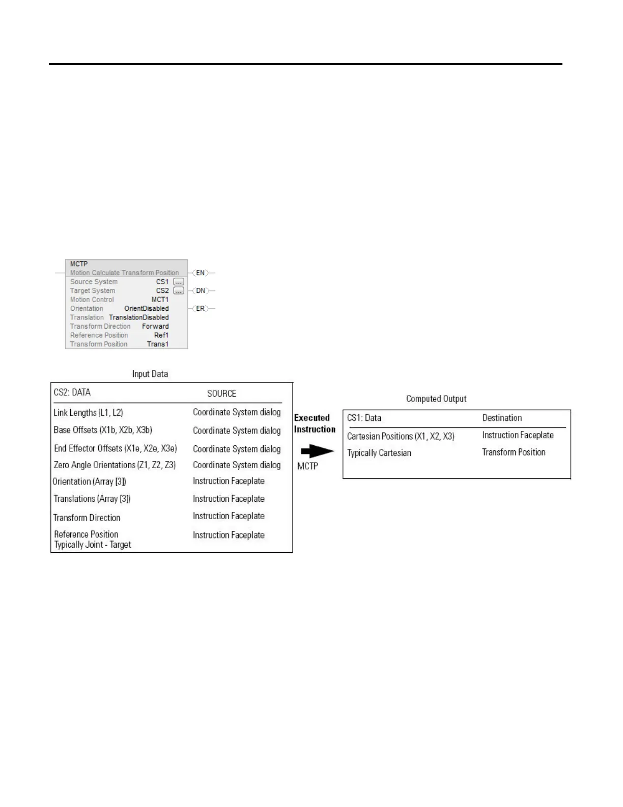
Data Flow of MCTP Instruction Between Two Coordinate Systems
The following illustrations show the flow of data when an MCTP Instruction is
executed to perform a forward transformation and an inverse transformation. The
CS1 indicator represents a Cartesian coordinate system containing X1, X2 and X3
axes as the source of the MCTP instruction. The CS2 indicator represents the
joint coordinate system containing J1, J2 and J3 axes as the target of the MCTP
instruction.
Data Flow When a Move is Executed with an MCTP Instruction - Forward
Transform

Table of Contents

Other manuals for Allen-Bradley Studio 5000 Logix Emulate

Questions and Answers:

Question and Answer IconNeed help?

Do you have a question about the Allen-Bradley Studio 5000 Logix Emulate and is the answer not in the manual?

Allen-Bradley Studio 5000 Logix Emulate Specifications

General IconGeneral
BrandAllen-Bradley
ModelStudio 5000 Logix Emulate
CategoryController
LanguageEnglish

Related product manuals