Chapter 4: Installing the Switch on a Table or in an Equipment Rack
66
Steps 4 to 6 remove the plastic feet from the bottom of the switch.
You must remove the plastic feet to install the switch in the AT-
RKMT-J15 Bracket.
4. Place the switch upside-down on a table. Refer to Figure 33.
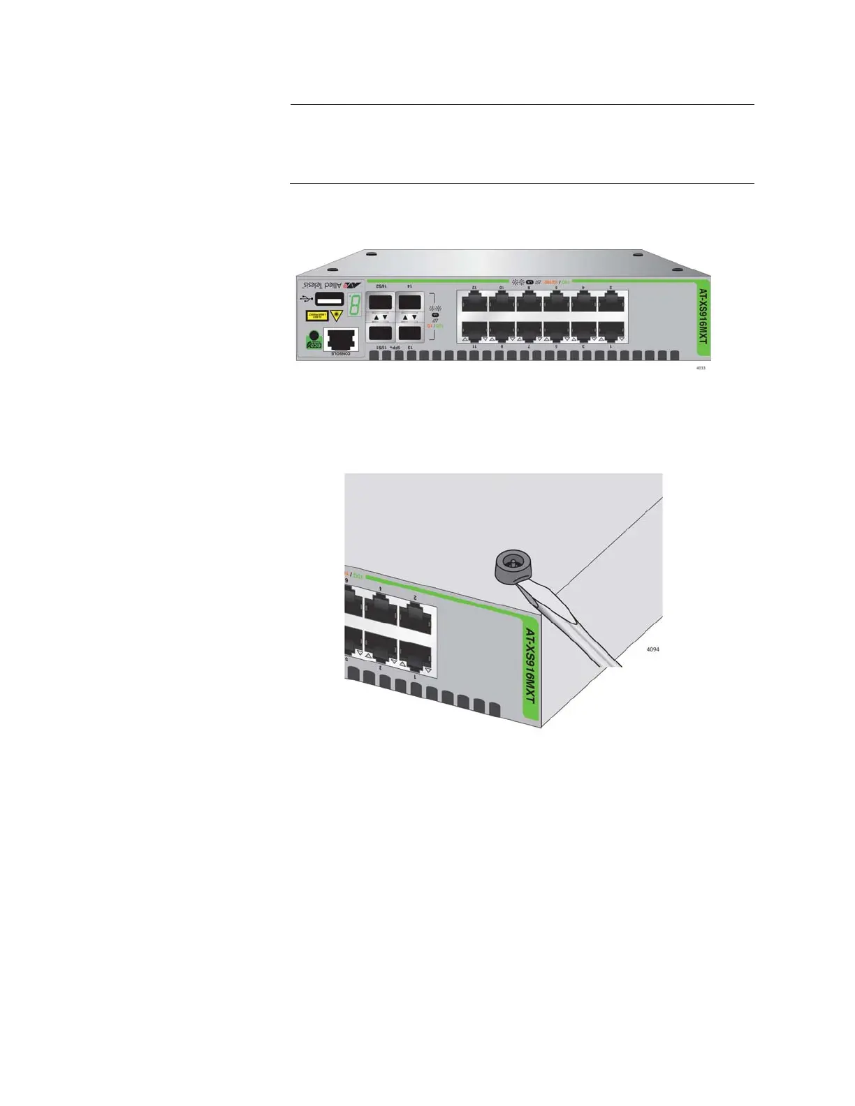
Figure 33. Turning the Switch Upside Down
5. Use a small flat-head screwdriver to pry the four plastic feet from the
bottom of the switch. Refer to Figure 34.
Figure 34. Removing the Plastic Feet from the Bottom Panel of the Switch
6. Turn the switch over so that it is right-side up.
7. Place the switch in the left or right side of the bracket, with its front
panel facing the front of the bracket. If you are installing only one
switch, you can install it on either side. Refer to Figure 35 on page 67.

 Loading...