0180036-J0 Rev E Page 33
Wiring Connections: HV ADIO
CAUTION: For HV-ADIO wiring only use 600V rated insulation for any HV signals.
13, 14 and 15; K4 Relay 4 NC / COM / NO 60Vdc / 1A
16, 17 and 18; K5 Relay 5 NC / COM / NO 60Vdc / 1A
19, 20 and 21; K6 Relay 6 NC / COM / NO 60Vdc / 1A
64, 65 and 66; K7 Relay 7 NC / COM / NO 60Vdc / 1A
67, 68 and 69; K8 Relay 8 NC / COM / NO 60Vdc / 1A
70, 71 and 72; K9 Relay 9 NC / COM / NO 60Vdc / 1A
73, 74 and 75; K10 Relay 10 NC / COM / NO 60Vdc / 1A
76, 77 and 78; K11 Relay 11 NC / COM / NO 60Vdc / 1A
79, 80 and 81; K12 Relay 12 NC / COM / NO 60Vdc / 1A
Digital Inputs
22 and 23; EXT LVD Open Pos (+) OR Neg (-) 0 - 60Vdc
24 and 25; D1 Digital Input 1 Pos (+) OR Neg (-) 0 - 60Vdc
26 and 27; D2 Digital Input 2 Pos (+) OR Neg (-) 0 - 60Vdc
28 and 29; D3 Digital Input 3 Pos (+) OR Neg (-) 0 - 60Vdc
30 and 31; D4 Digital Input 4 Pos (+) OR Neg (-) 0 - 60Vdc
32 and 33; D5 Digital Input 5 Pos (+) OR Neg (-) 0 - 60Vdc
34 and 35; D6 Digital Input 6 Pos (+) OR Neg (-) 0 - 60Vdc
36 and 37; D7 Digital Input 7 Pos (+) OR Neg (-) 0 - 60Vdc
38 and 39; D8 Digital Input 8 Pos (+) OR Neg (-) 0 - 60Vdc
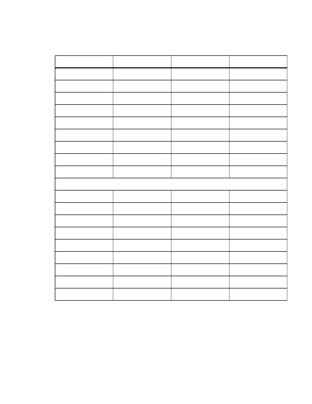
Table 5: Wiring Connections: L-ADIO (Continued) (Sheet 2 of 2)
Terminal Description Signal Type Range