%5HY
5.2 Wiring the External Batteries
:$51,1*
7KHEDWWHULHVPXVWEHLQVWDOOHGE\TXDOL¿HGSHUVRQQHOWUDLQHGLQWKHVDIHXVHRIKLJK
HQHUJ\SRZHUVXSSOLHVDQGWKHLUEDWWHULHV5HIHUWRWKHVDIHW\VHFWLRQLQWKLVPDQXDO
• Use new batteries when installing a new unit. Verify that all batteries are the same type with identical date
codes.
• For the FXM 650-24, the battery string is 24 VDC. For the FXM 650-48/1100/2000, the battery string is 48
VDC.
• If you are making your own battery wiring harness, use at least 10 AWG (for FXM 650/1100) or 8 AWG (FXM
2000) wires.
• The battery return connection is to be treated as an Isolated DC return (DC-I) as defined in GR-1089-CORE.
5.2.1 Procedure
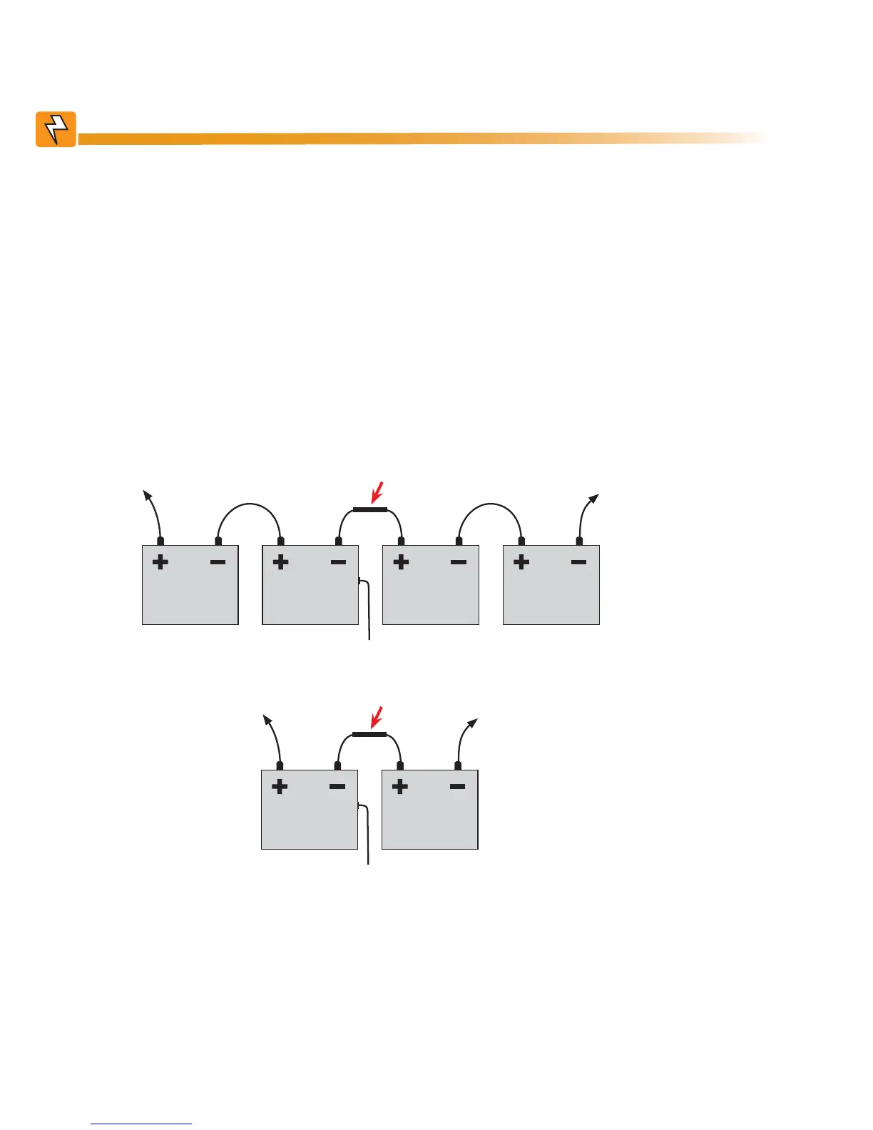
1. For FXM 650-48/1100/2000 (48 V battery string), number the batteries from 1 to 4 with labels or tape. For
FXM 650-24 (24 V battery string), number the batteries from 1 to 2 as shown in the figure below.
)LJXUH ² ([WHUQDO%DWWHU\:LULQJIRU9'&VWULQJWRSDQG9'&VWULQJ
Tape the battery temper-
ature sensor to the side
of either battery #2 or #3.
%DWWHU\ %DWWHU\ %DWWHU\ %DWWHU\
To positive terminal
To negative terminal
Optional in-line fuse
Tape the battery temperature
sensor to the side of either bat-
tery #2 or #1.
%DWWHU\ %DWWHU\
To positive terminal
To negative terminal
Optional in-line fuse