Maintenance
Electrical contact densimeter threshold in sp ectio n
L51--107EN/01
7/8
06--2003
E ALSTOM
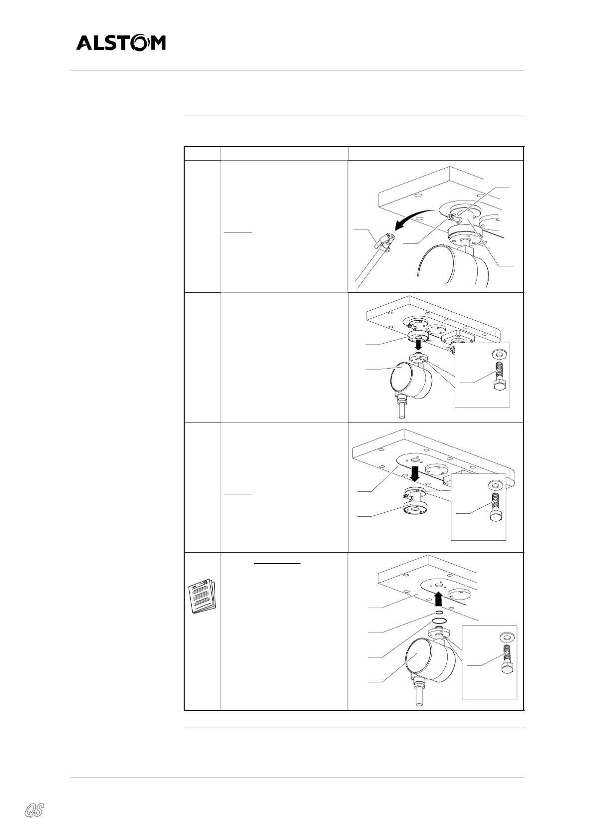
Replacing th e densimeter
Process
The table below gives the process to replace the densimeter :
Step Action Diagram
1 Disconnect the pipe (6)
from the valve (24) of the
connection valve block (5).
Screw the valve--cap (25)
on the valve (24).
NOTE
: Keep the end of
the tube (6) in high posi-
tion to keep the SF
6
gas
which it contains and to
prevent damp air from
entering.
25
6
5
24
2 Remove the densimeter
(1), held in place by screws
(15), on the connection
valve block (5).
x3
15
HM6--20
5
1
3 Remove the connection
valve block (5), held inplace
by screws (8), on the hous-
ing cover (2) of the circuit--
breaker.
NOTE
: If the connection
valve block (5) is any
more used, see the next
paragraph “Putting away
the control tool”.
x3
8
HM6--20
2
5
4 Install new seals (26) and
(27) on the densimeter (1),
referring to “Preparing and
installing static seals” in
”Erection general proce-
dures”.
Install the densimeter (1) on
the housing cover (2), of the
circuit--breaker , using
screws (8).
x3
8
HM6--20
0,7 daN.m
26
1
2
27