COMBITHERM® SERVICE and TROUBLE SHOOTING
COMBITHERM INSTALLATION AND MAINTENANCE MANUAL #6004/18
PG. 20
WATER TROUBLE
1. Low-Water LED light remains
flashing.
2. Low-Water LED does not
illuminate.
3. Inner oven cavity flooded with
water.
4. Low-Water LED light remains
flashing and signal beeps.
STEAM GENERATOR TROUBLE
5. Steam LED light does not
illuminate and flash after
initial oven start-up or
illuminates and keeps flashing
after 5 minutes.
a) Drain cap of steam generator
in the interior of the oven
compartment is open.
b) Seal of drain cap is leaking.
c) Water supply to unit is closed.
d) Dirt is blocking strainer in
water supply line.
e) Dirt is blocking strainer in
front of solenoid valve.
f) Solenoid valve Y1 does not
open.
g) Magnetic coil on solenoid
valve Y1 is defective.
h) Solenoid valve is defective.
i) Relays on PC board defective.
a) Water level probe is dirty.
b) Water level probe is defective.
c) Bad wire connection to water
level probe.
d) Bad wire connection between
B1/B2 and multi-pin plug
X8/3 and X8/4 on PC board.
a) Oven drain is blocked.
a) Incorrect wire connection to
water level probe.
a) Safety thermostat (N5) for
immersion heater shut off.
b) Sensor B4 is defective.
c) Loose wires on the main
control board.
d) Contactors for K1/K2/K3
immersion heating element are
not operating.
e) PC board is defective.
Hand-tighten drain cap.
Replace seal.
Open tap.
Clean strainer.
Clean strainer.
Check for continuity between Y1
and multi-pin plug X5/1 and
X5/10 on PC board.
Replace coil.
Replace solenoid valve.
Replace PC board.
Clean water level probe.
Replace water level probe.
Check wire connection:
Black Wire = Low Water Level
White Wire = Normal Water Level
Check wire connection.
Clean oven strainer.
Clean oven drain.
Clean floor drain.
Check wire connection:
Black Wire = Low Water Level
White Wire = Normal Water Level
Push red button on safety
thermostat (N5).
Replace sensor B4.
Check connections X8/7 and X8/8.
Check continuity between block
terminal 22 and 25, and contactors
K1/K2/K3.
Check continuity between K1A1
and X5/6.
Check continuity between K2A1
and X5/7.
Replace the PC board.
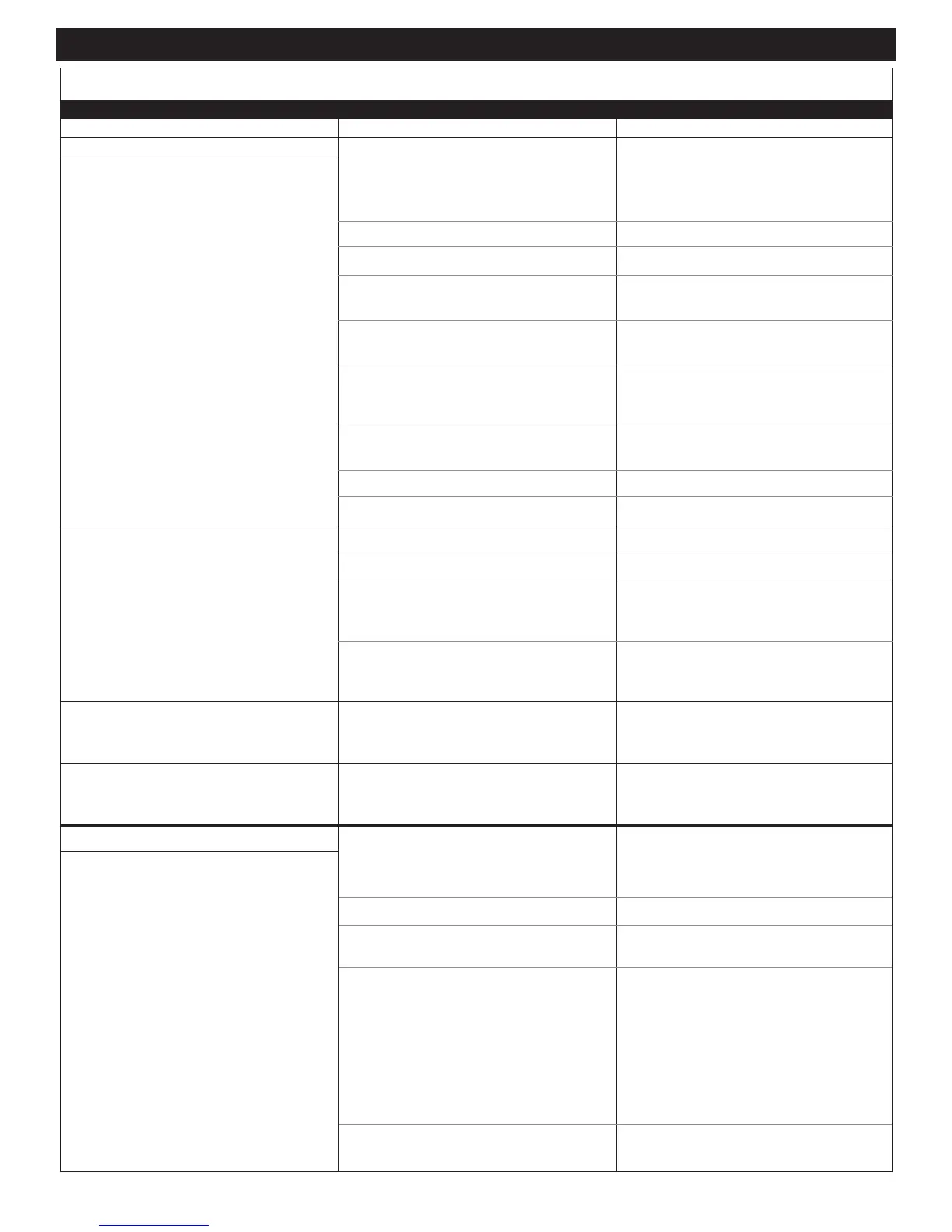
TROUBLE SHOOTING CHECKLIST
PRIOR TO STARTING SERVICE WORK, OVEN MUST BE DISCONNECTED FROM THE POWER SOURCE.
PROBLEM POSSIBLE CAUSE REMEDY
 Loading...