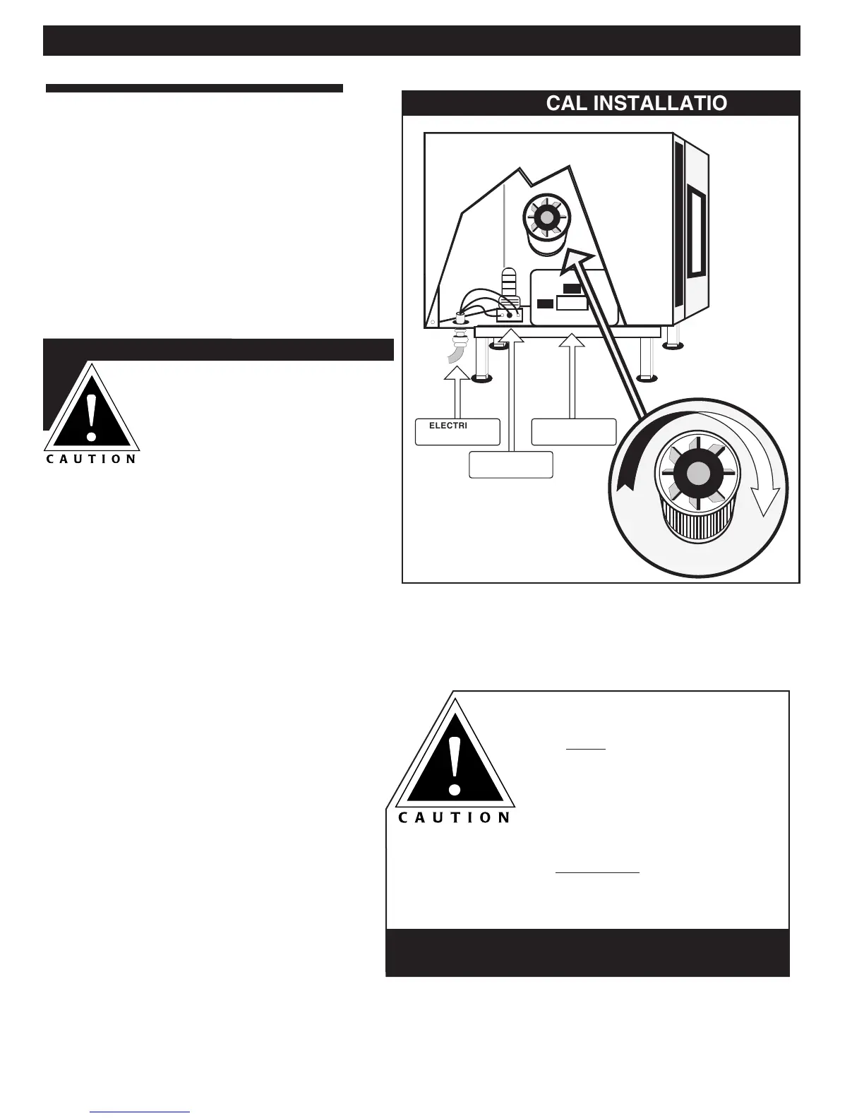
FOLLOWING ELECTRICAL CONNECTION,
THE FAN MUST ROTATE IN THE SAME
DIRECTION AS THE ARROW
LOCATED ON THE OVEN FAN
MOTOR.
THIS APPLIANCE WILL NOT FUNCTION
PROPERLY AND DAMAGE CAN OCCUR IF
THE MOTOR ROTATION IS NOT CORRECT.
COMBITHERM® INSTALLATION and SPECIFICATIONS
ELECTRICAL INSTALLATION
An electrical wiring diagram is located behind
the control panel on the left side of the oven.
The oven must be installed by a qualified
electrician. This appliance must be branch
circuit protected with proper ampacities, in
accordance with the wiring diagram located in
the electrical compartment of the oven. The
oven must be properly grounded in accordance
with the National Electrical Code and
applicable local codes.
CAUTION
ENSURE THE AVAILABLE
POWER SOURCE MATCHES
THE VOLTAGE STAMPED
ON THE NAMEPLATE OF
THE OVEN.
Wire size posted for the main incoming power
to the unit must match the minimum size listed
in the specifications applicable to the specific
oven model. For supply connections, locate the
wire size posted on the label located on the
electrical control box cover, behind the service
panel or elsewhere listed in this manual.
When connecting to a Delta-B (wild leg) on a 3-
phase system, the wild leg must be connect to
line 3.
Before operating the oven, check all cable
connections in the electrical connection area for
tightness since connections can loosen during
transport.
 Loading...