18
The following interface is based on the 8-channel advanced 1080P (V2) mini 1U Series. Note:
The 32-channel alarm interface diagram is shown below, on page 38.
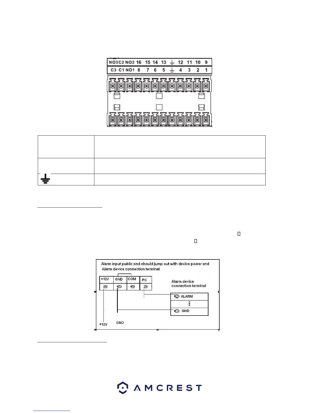
3.3.4.5 Alarm Input Ports
• Grounding alarm inputs. (Normal Open or Normal Close type)
• Please parallel connect COM end and GND end of the alarm detector (Provide external power to the alarm
detector).
• Please parallel connect the Ground of the DVR and the ground of the alarm detector. Please connect
the NC port of the alarm sensor to the DVR alarm input (ALARM) Use the same ground with that of
DVR if you use external power to the alarm device.
3.3.4.6 Alarm Output Ports
• Provide external power to any external alarm device.
• To avoid overloading, please read the following relay parameters sheet carefully.