Version 0A 26
change moving between 30 and 20, 17 and 15, or 12 and 10-meter selections since
these band groups share a common filter in each pair.
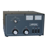
Set the BAND switch (Figure 3, #2) to a band where you have a good 50-ohm high-
power load connected.
Change the meter switch (Figure 3, #6) to REF. In this position, the multimeter indicates
PEP reflected power.
The next objective is to have a steady unmodulated low-power carrier. With no
modulation in the FM, AM, RTTY, or CW mode, and with the amplifier still on standby,
adjust the exciter’s power to about ten watts. Verify your radio is supplying reduced
power, ideally around 10-20 watts carrier (not critical), and that VSWR of the antenna
system or load is low. There should be almost no deflection on the reflected power
scale (Figure 3, #1) with the MULTIMETER switch in the REF position. If the meter
indicates noticeable reflected power, check the RF cables or antenna system.
Reminder: You cannot use a tuner in your radio or between your radio and this
amplifier to match the antenna system. Any antenna matching must be between
the amplifier and the antenna, and the antenna tuner and everything else
connected beyond the amplifier must conservatively handle 600 watts of both
carrier and peak envelope power.
ɀ Place the amplifier in OPERATE position (Figure 3, #7). Be sure the amplifier
BAND SELECT (Figure 3, #3) matches the band selected on the transceiver.
ɀ Place the transmitter or transceiver into transmit in FM, AM, RTTY, or CW
modes. The green TX LED (Figure 3, #5) should light. The Forward (KW) power
scale (Figure 3, #1) should increase to very roughly ten times the initial exciter
power reading. Reflected power should remain very low, and the PA current
should increase on the right meter 0-70 scale (Figure 3, #1) when in the Id
Multimeter position. Only the TX and BAND SELECT LED’s should illuminate.
ɀ Briefly, increase exciter power until the amplifier reaches 600-watts output, or
increase power until the exciter reaches maximum power without exceeding 600-
watts amplifier power. Watch the Id MULTIMETER position on the right meter 0-
70 scale, and never exceed 30 amperes. Target Id reading is 25 amperes or
less.
ɀ After verifying all of this, and understanding control locations and function, the
amplifier is ready to operate.
ɀ This amplifier produces approximately 600-watts PEP output power with
approximately 70-watts PEP drive. This is nominal power, and can vary slightly
from band-to-band.
ALC Adjustment
It is unfortunate, but radio manufacturers do not have standardized interfaces. Because
of this, ALC requires some initial adjustment. If the ALC voltage is too low, the ALC will
not provide good control of power levels. If the ALC loop gain is too high, the ALC can
cause a “power bounce” as power attempts to settle at the desired ALC power