Version 0A 27
threshold. This overshoot, dip, and recovery is caused by slow radio ALC response
time. Excessive ALC control loop gain aggravates power bounce.
ALC attack bounce shows on a steady carrier (such as RTTY, CW, or FM) as a high
initial peak power reading followed by a deep null. The deep null is followed by a slow
settling to the desired power level. On SSB, it will show as a slow warble or modulation
of power levels, especially at the very start of voice transmissions.
If ALC attack bounce is observed, the ALS-606 will require ALC gain adjustment. The
ALS-606 has a small flat-blade screwdriver adjustment for setting ALC gain. This
adjustment is accessible through a small hole located on the left cabinet side behind the
front panel, near the panel meter.
Power Supply Line Voltage Settings
ALS-600PS Voltage Settings
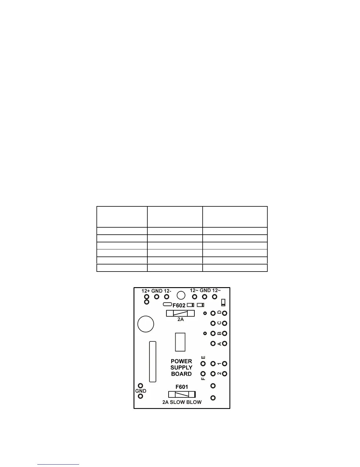
Before opening up the ALS-600PS make sure the supply is unplugged. On the ALS-
600PS there are several solder on jumpers to set the line voltage range. Change the
jumpers only if the line voltage is low. For most cases, unless you need to change over
to 220VAC there should not be a need to change the jumpers.
Table 4 ALS-600PS Voltage Settings
Figure 5 ALS-600PS Board
AC LINE
VOLTAGE
RANGE
PRIMARY
BUCK BOOST
95-110 A to B C to D E to 2 F to 1
105-120 A to B C to D E to F
115-130 A to B C to D E to 1 F to 2
200-220 B to C E to 2 F to 1
210-230 B to C E to F
220-240 B to C E to 1 F to 2
 Loading...