Version 0A 31
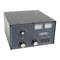
CB2
The CB2 is located on the amplifier side between the band selector and power jack,
below the attenuator board. The CB2 control board provides most control functions,
including bias, fan speed, overload, wrong-band protection, and transmit-receive relay
sequencing. It is the hub for nearly all functions, including external interfaces, power
metering, and 12-volt busses.
MB2
The MB1 is located behind the front panel below the meter. It contains peak-envelope-
power detection circuits, multi-meter switching, fault indicators, and ALC circuitry. There
are four power meter adjustments on this board; forward power, reflected power,
forward peak hold time, and reflected peak hold time. Shunts on a header, located on
the board’s upper edge, adjust panel meter brightness. This board also contains an ALC
gain adjustment, which limits ALC voltage.
PAM-606
The PA board, along with a large forced-air cooled heatsink, forms a PA module. FET’s
are gain matched at the factory, and replacement FET’s must be gain matched. This
board does not have adjustments; bias adjustments are located on the CB2. The power
amplifier module (located between the filter chassis and the cabinet bottom) is
accessible by removing the amplifier bottom cover only. The cabinet bottom cover must
remain in place to support the rest of the sheet metal.
PD8m
The PD8m is located on the right side of the amplifier just above the panel containing
the cooling fans. This board is slightly reconfigured from the PD8 used in the ALS1306
through removal of the matching transformer and combiner. The PD8m contains two
3dB attenuator pads. One attenuator switches out to increase six meter gain. Do not
modify, remove, or bypass the attenuators.
RJ45
The RJ45 board mounts on the rear panel. It contains two RJ-45 jacks for remote
control interface.
RLY
The RLY board contains independent transmit and receive relays, one for RF output
switching and the other for RF input switching. T/R relays activate with a low on
terminals K (key) J1-3 and RJ1-7. The CB2 board contains relay timing logic.
SWR
The SWR board is on the rear panel in front of the RF output connector. It is a traditional
50-ohm directional coupler. The null adjustment is accessible through a rear panel hole.
 Loading...