16 | 5000 Single-Point Moisture Analyzer
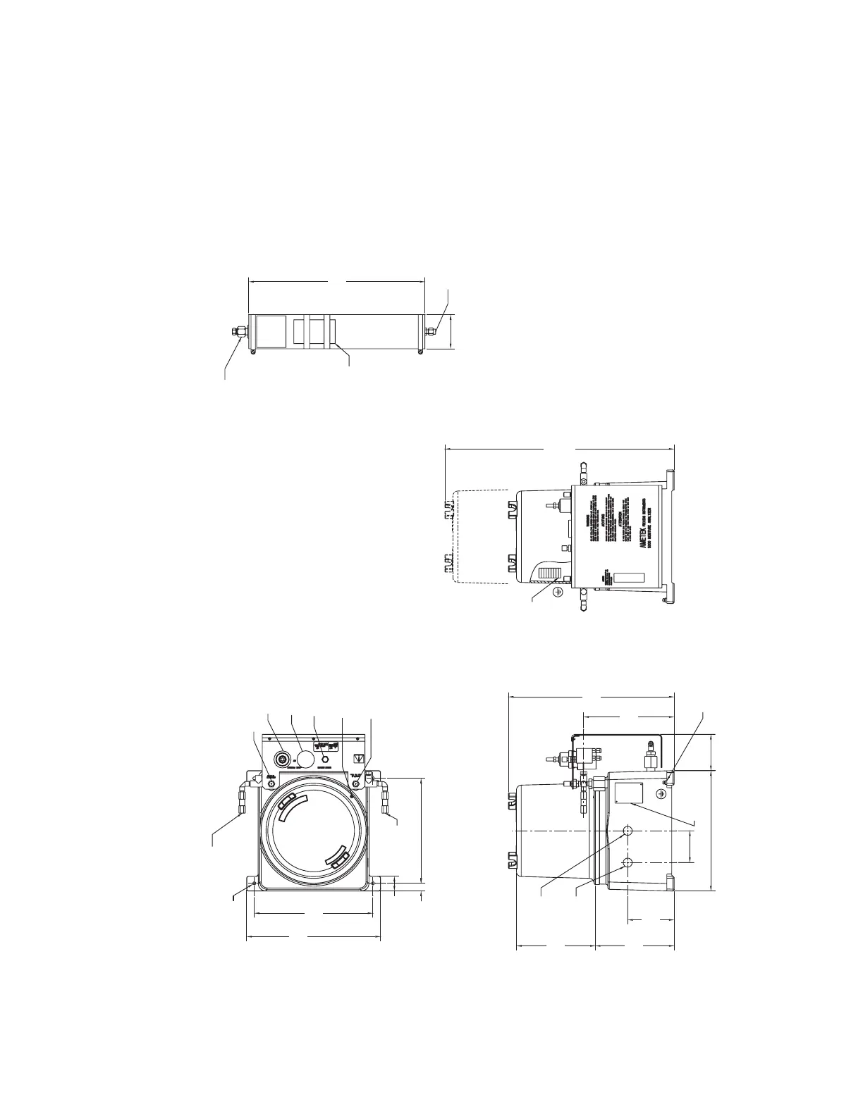
Field Unit Installation
Figure 3-1 shows installation dimensions for standard (Division 1 and 2) and Zone 1 ver-
sions of the field unit. Locate the field unit as near as possible to the sample tap and bolt
into place. The unit should be protected from direct exposure to weather and located so
that the ambient temperature specifications will not be exceeded.
TB1
LOCATED BEHIND TB1
GROUND CONNECTION
DRYER
100 PSIG
MAXIMUM PRESSURE
WARNING
THIS END UP
LABEL
CERTIFICATION
CENELEC
SEE NOES 2 & 5
1/8" TB FTG
WET GAS IN
SEE NOTES 4 & 6
DRYER (TYP)
[3.50]
89
1/8" TB FTG, SEE NOTES 2 & 5
DRY GAS OUT TO ANALYZER
SEE NOTE 2
[18.00]
457
7. FIELD UNIT EQUIPPED WITH CENELEC REQUIREMENTS PER EN500812.
SUPER-ACTIVATED MOLECULAR SIEVE DRYER.
6. THE SAME DRYER DIMENSIONS CAN BE USED FOR CONTAMINANT TRAP AND
PROLONG EXPOSURE TO MOIST AIR MAY REDUCE DRYER LIFE.
PRIOR TO INSTALLATION. MINIMIZE INTERNAL CONTACT WITH AMBIENT MOISTURE.
5. REMOVE DRYER SEAL PLUGS AND INSTALL SUPPLIED NUTS AND FERRULES JUST
4. POSITION VERTCALLY WITH END UP AS NOTED ON BODY.
MINIMIZE TUBE LENGTHS.
3. CUSTOMER TO MOUNT DRYER CHAMBER TO 5000 ANALYZER FIELD UNIT TO
2. FERRULES AND NUTS ARE PLACED IN PLASTIC BAG AND ADHERED TO DRYER.
1. XXX DIMENSIONS ARE IN MILLIMETERS. (XXX) DIMENSIONS ARE IN INCHES.
NOTES:
L
C
3/4-14 NPT
SIGNAL
3/4-14 NPT
POWER
GROUND LUG
FRONT VIEW
LEFT SIDE VIEW
TOP VIEW
GENERATOR FLOW ADJUSTMENT
1/8" NPT(F)
SAMPLE IN,
FROM CONDITIONED SOURCE
REFERENCE INLET, 1/8" NPT(F)
SAMPLE ADJUSTMENT
5mm HEX
LOCKING SCREW
BACK PRESSURE GAUGE
BACK PRESSURE ADJUSTMENT
REFERENCE ADJUSTMENT
CLEARANCE
MINIMUM
[28.00]
711
[9.26]
235
[16.94]
430
[8.06]
205
[8.06]
205
[4.75]
121
[3.71]
94
[3.25]
83
[12.32]
313
[Ø.31]
Ø8
[10.75]
273
4 PLACES
[.78]
20
4 PLACES
[1.51]
38
[13.69]
348
[12.13]
308
Figure 2.
Installation / dimensional layout for
Model 5000 field unit (Zone1)