2.1 Main Display
Figure 3. Display
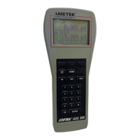
The display of the calibrator, shown in Figure 3, is divided into three main
sections: the upper display, the lower display, and the menu bar.
The upper display is used for measuring dc voltage, dc current with and
without loop power, and pressure.
The lower display can be used for both measuring and sourcing.
The menu bar is used to setup both the upper and the lower display to
perform the desired function.
Table 3 explains the different parts of the display:
Table 3: Display Functions
No. Name Description
1 Primary Parameters Determine what parameter is going to be
measured or sourced.
The available options for the upper display
are:VOLTS IN, PRESSURE, mA IN, and mA
LOOP.
The available options for the lower display
are:VOLTS, TC (thermocouple), RTD, FREQ
(frequency), PULSE, PRESSURE, mA, and
mA 2W SIM.
2 Input/Output control Switches the lower display between input
mode (read), and output mode (source).
3 Additional Settings Available only for TC (thermocouple), and
RTD measurements. For TC this setting
turns the CJC (Cold Junction Connection)
on and off.
For RTD measure [RTD IN], his setting sets
the number of wires used in the measure-
ment (2-wire, 3-wire, or 4-wire)
7
 Loading...