32 23-03-2009 105446 06
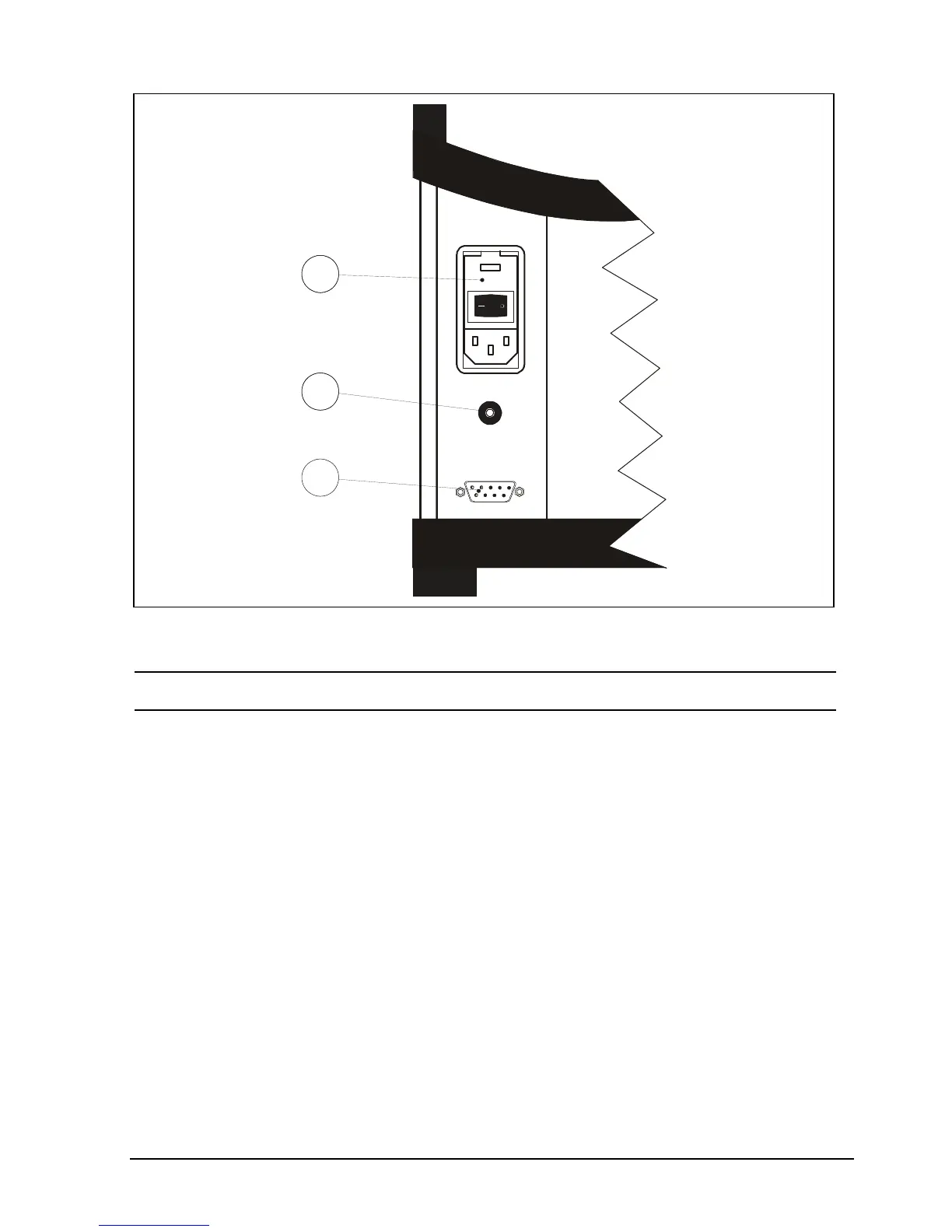
Standard connections (all versions)
Fig. 5
Pos. Description
Power control switch with a cable connection and on/off
switch. It also contains the main fuse. See section 6.1 for
information on how to change the fuses and section 3.2.1
to adjust the voltage setting of the power control switch.
Connection for synchronization output.
The state of the synchronization output is determined by
the READ or TRUE temperature (dependent on the choice
of reference sensor) by the following guidelines:
When the extended stability time is = 0 minute, the
relay is switched on for 2 seconds, when stability is
achieved.
When the extended stability time 1 minute for the
internal reference sensor (READ), the relay is switched
on in the last minute of the extended stability time.
Sync.
230V 5AF/115V 10AF
115 V
Fuse
RS232
1
2
3
 Loading...