34 23-03-2009 105446 06
Pos. Description
Input for RTD sensor (2, 3 or 4 wire).
Connection to chassis (earth/ground).
Input for reference sensor.
Voltage input.
Passive mA input.
Active mA input with 24V supply for transmitter.
Connection for thermostat test.
Note that this connection is for dead switches.
TC connection for thermocouples.
One of the inputs either
, , , or can be selected
displaying the “SENSOR” temperature in the Setup and
can be
displayed as “TRUE” temperature.
Note: Only the sensor type, which is to be tested, should be connected
to the input panel.
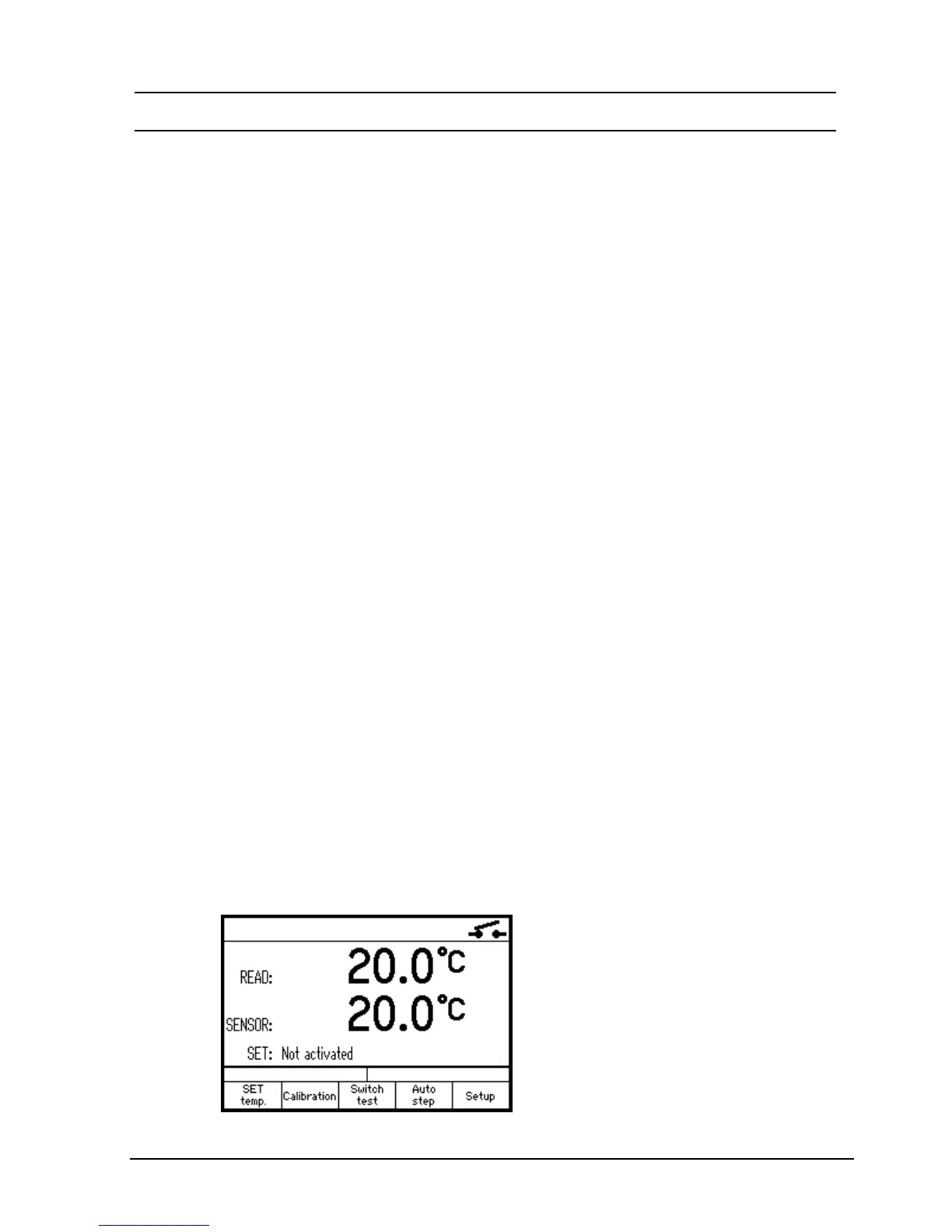
4.3 Display readouts
Switch on the calibrator using the power control switch (pos.
1 in fig. 5). The start up menu is displayed for approximately
2 seconds and is then replaced with the main menu screen:
 Loading...