EasyManuals Logo

Ametek MFC 1000.1 User Manual

Ametek MFC 1000.1
37 pages
To Next Page IconTo Next Page
To Previous Page IconTo Previous Page
Page #10 background imageLoading...
Page #10 background image
AMETEK CTS H-Field Test
Operating Manual V 1.20 10 / 37
1.4.2.
Current transformer MFT 30
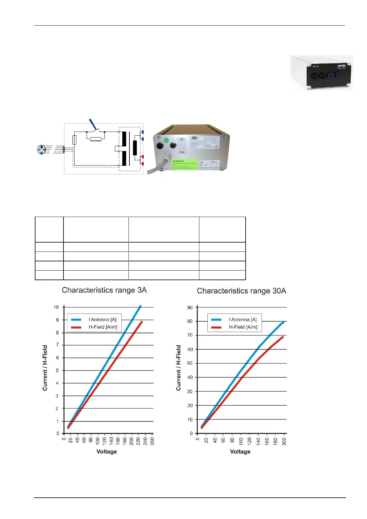
The MFT 30 has two current ranges 3 A and 30 A. The ranges can be select with the switch
at the rear side of the MFT 30. The two parallel current outputs to the antenna can be used
with connectors for 4 mm or 50 A.
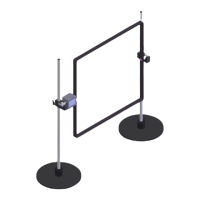
The V/I characteristic of the transformer determines the voltage at the output of the variac to
generate the specified magnetic field. because the magnetic field antenna has a very small
impedance the impedance of the wiring mostly determines the V/I characteristic of the current
transformer.
Transformer Factors
 A : approx.. 0.043 A/V
0A : approx.:0.434 A/V
Diagram and Current factor of MFT 30
The following table shows the voltage setting in dependency to the selected current range:
H-field
[ A/m]
Range 3 A
Primary voltage at
MFT 30 [V]
Range 30 A
Primary voltage at
MFT 30 [V]
Antenna
current [A]
1
26.8
1.15
3
80.0
7.5
3.46
10
(263)
25.5
11.5
30
77.5
34.48
230V
0...3A/m 0...30A/m

Table of Contents

Questions and Answers:

Question and Answer IconNeed help?

Do you have a question about the Ametek MFC 1000.1 and is the answer not in the manual?

Ametek MFC 1000.1 Specifications

General IconGeneral
BrandAmetek
ModelMFC 1000.1
CategoryMeasuring Instruments
LanguageEnglish

Related product manuals