AMETEK CTS H-Field Test
Operating Manual V 1.20 18 / 37
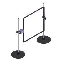
Test setup with MFT 100 for H-Fields up to 1.000 A/m
Variant 1: variac NX 1-260-xx not Rack connected (MFT 100)
Disable option Rack connected
Switch PF2 is used to switch the relay in the MFT 100 with the mains voltage, thus switching the test on/off.
Switch PF1 is not required for this test and remains open. The controlled variable is fed directly from the PF2/N
output on variac NX to the MFT 100.
Schematics and Test setup with compact NX, variac NX1-260-16, MFT 100 and MFC 1000.x
Option for required magnetic field tests as per IEC 61000-4-8
- External variable motor transformer variac NX1-260-16
- External Magnetic field antenna MFC 1000.x
- External current transformer MFT 100 to test 100 A/m (continuous) and up to 1.000 A/m (short-term)
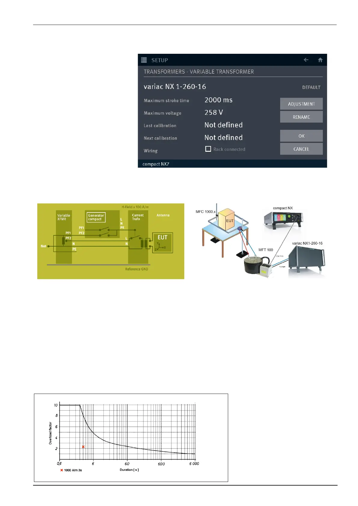
Tests with 1.000 A/m magnetic field
During tests with a field of 1.000 A/m the primary current of variac NX1-260-16 during the 3s testtime goes to
approx. 39A. The motorvariac can withstand this load for this short time. The figure below shows the load diagram.
Therefore, the variac NX1-260-16 can withstand during approx. 45s a current of 39A. Normally the fuses do not
break during the 3s test time.
Load diagram variac NX1-260-16
 Loading...


