Do you have a question about the Ammann Cummins ASC110 and is the answer not in the manual?
Guidance on safe practices for equipment repair and inspection, including personal protective equipment.
Precautions for safe handling of hydraulic and fuel systems.
Safety for welding, seal usage, and tightening torque guidelines.
Guidelines for personal hygiene, environmental protection, and fire prevention during repairs.
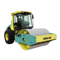
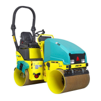
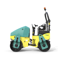
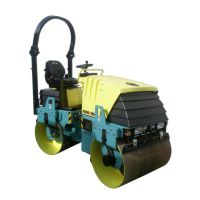
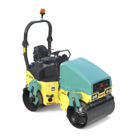
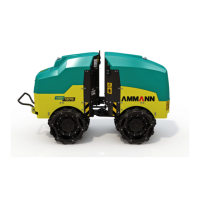
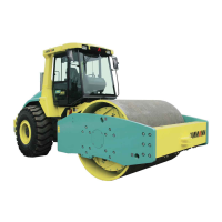
General information about the machine, its description, and application.
Illustrations of name plate location and a chart providing dimensional specifications.
Data on weight specifications and driving characteristics for various ASC 110 models.
Details on engine, axle, brakes, vibration, fluid capacities, and wiring.
Data on noise/vibration emissions and list of optional equipment available.
Step-by-step instructions for disassembling and assembling the engine, including preparatory setup.
Technical specifications for the drum, including service fluids and lubricating grease.
Step-by-step instructions for safely dismounting the drum from the machine.
Procedures for mounting vibration plate, bearings, seals, and the drum into the frame.
List and illustrations of fixtures used during drum dismounting and mounting operations.
Explanation of the articulated joint's function and machine preparation steps for service.
List and illustrations of fixtures used for servicing the articulated joint.
Procedures for removing coupling components and assembling the clutch.
Specifications for clutch bolt torque and notes on adhesive application, plus required fixtures.
Procedure for removing the linear hydraulic motor and replacing its seals.
Instructions for assembling hydraulic cylinders, including seal kits and torque specifications.
List and illustrations of fixtures used for hydraulic cylinder service.
Description of travel control, its brake function, and steering column removal.
Steps for removing and reassembling the travel control and adjusting the brake.
Instructions for removing cabin components like the front wiper, fan, and rear window wiper.
Steps for removing the driver's station platform, including loosening bolts and disconnecting wiring.
Procedure for draining coolant and lifting the cab for heater access.
Steps for removing heater unit, hoses, and details on the AC system.
Identification and function of fuses in the machine's electrical system, including engine fuses.
Instructions for master switch operation and replacing instrument panel components.
Diagrams showing component locations and guidance on battery/alternator/starter systems.
Steps for suspending and loosening bolts to remove the ROPS frame from the machine.
Instructions for installing segments onto the drum surface, including tightening and checking connections.
Procedure for placing segments and mounting scrapers onto the drum and frame.
Steps for supporting the frame, removing bolts, and servicing the tire and disk.
List and illustration of fixtures used for wheel disassembly.
Procedure for removing hood and cabin hydraulic motors, including lifting, support, and pin removal.
Procedure for removing linear hydraulic motor and replacing its seals.
Instructions for assembling hydromotors, including torque specs, seal kits, and required fixtures.
Steps for filling the hydraulic system with oil, including connecting the pump hose and monitoring the level.
Procedure for removing the level gauge cover, disconnecting wiring, and loosening attachment bolts.
Steps for removing the floater cover and replacing the fuel gauge.
Detailed steps for setting up and calibrating the fuel gauge using the POWER VIEW instrument.
Description of the electrical system and diagrams showing component locations.
Legend explaining symbols and the overall wiring diagram of the machine's electrical systems.
Diagrams illustrating the hydraulic systems for wheel and interaxle differential locks.
Standard test points and pressure specifications for diagnosing hydraulic system issues.
Procedures for adjusting hydraulic systems, vibration frequency, and precautions for towing.
Table of torque values for various bolts, screws, and hose connections.
Torque values for threaded connections with sealing edges and flat gaskets.
Standard hand signals for commands, driving, and movements.
Hand signals for indicating short movements, engine start, and engine cut-off.
| Brand | Ammann |
|---|---|
| Model | Cummins ASC110 |
| Category | Construction Equipment |
| Language | English |