10
4.6 CONNECTIONS
To avoid any problems while starting up the
machine , it is sug gested to follow what is
described below.
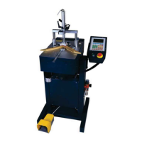
4.6.1 Pneumatic connection
Unscrew the lubricator bowl out from the air
lte r lub ricator.”C”
Fill the bowl with lubricating oil up to the
level m ark.
Scre w t h e “A” pressure gauge on the air lter
Scre w t h e “B” fast clutch tting normally
supplied or another suitable with the erising
system. (See picture 3)
Connect the feed line to the tting. (See
picture 4)
In the lubricator it is
advisable to use lubricant type
CASTROL MAGNA GC 32 o r a n
eq u ivalent lubrican t. Don’tuse
generic lubricants !
The use of non-suitable lubricants
might damage the valves.
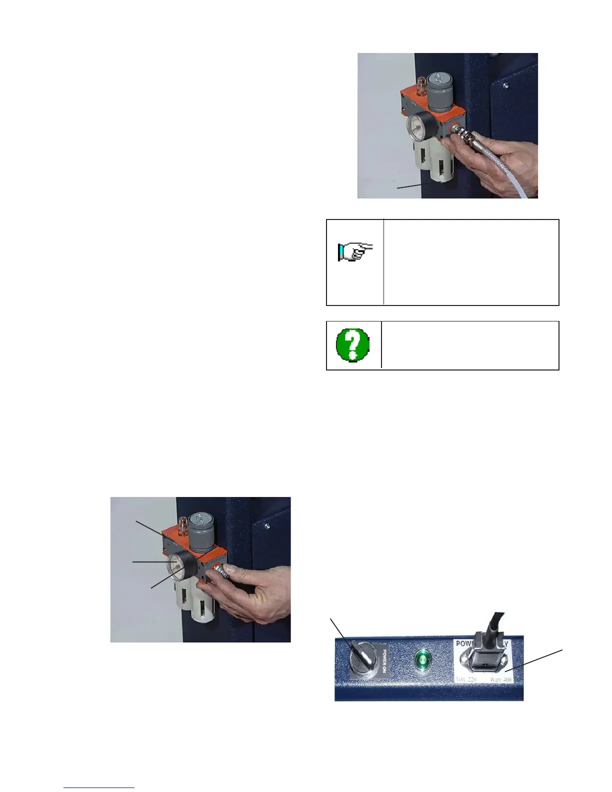
4.6.2 Electric connection
Check the network Voltage: it must be the same
of what indicated on machine cable (120 V).
Connect the power supplying cable to the plug
positioned on the machines rear side.
Avoid the use of long extension cables.
Pu t t he switch ( E ) on “1”which islocated on the oorstand
to switch on the machine.
Check that the green light next to the switch
is lit (if not, check the electric connections).
Rotate clockwise the emergency mushroom headed
button located on the keyboard.
Press the green button of the keyboard to
activate the keyboard controls.
4.3 PRELIMINARY ARRANGEMENTS
To install the machine it is necessary to prepare
a working area adequate to the machines
dimensions, lifting devices chosen and length
of mouldings to be worked.
4.4 UNPACKING
The machine is shipped on a wooden pallet,
packed into an appropriate carton and protected
with foam and polyurethane parts.
Remove the external packing and save it for
future use.
Check for any casual shipping damage and report
it immediately. Shipping damages or any other
defects must be reported to AMP within and
not later than 3 days from receipt of the
machine.
4.5 MACHINE POSITIONING
Position the machine in its working area.
Screw in the provided levelors to the oor
stand and level the machine by releasing or
tightening the levelors.
A
B
C
Picture 3
D
Picture 4
In order to eliminate the
condensation in the lter press
upwards on the “D” valve (see
picture 4).
D
E