4
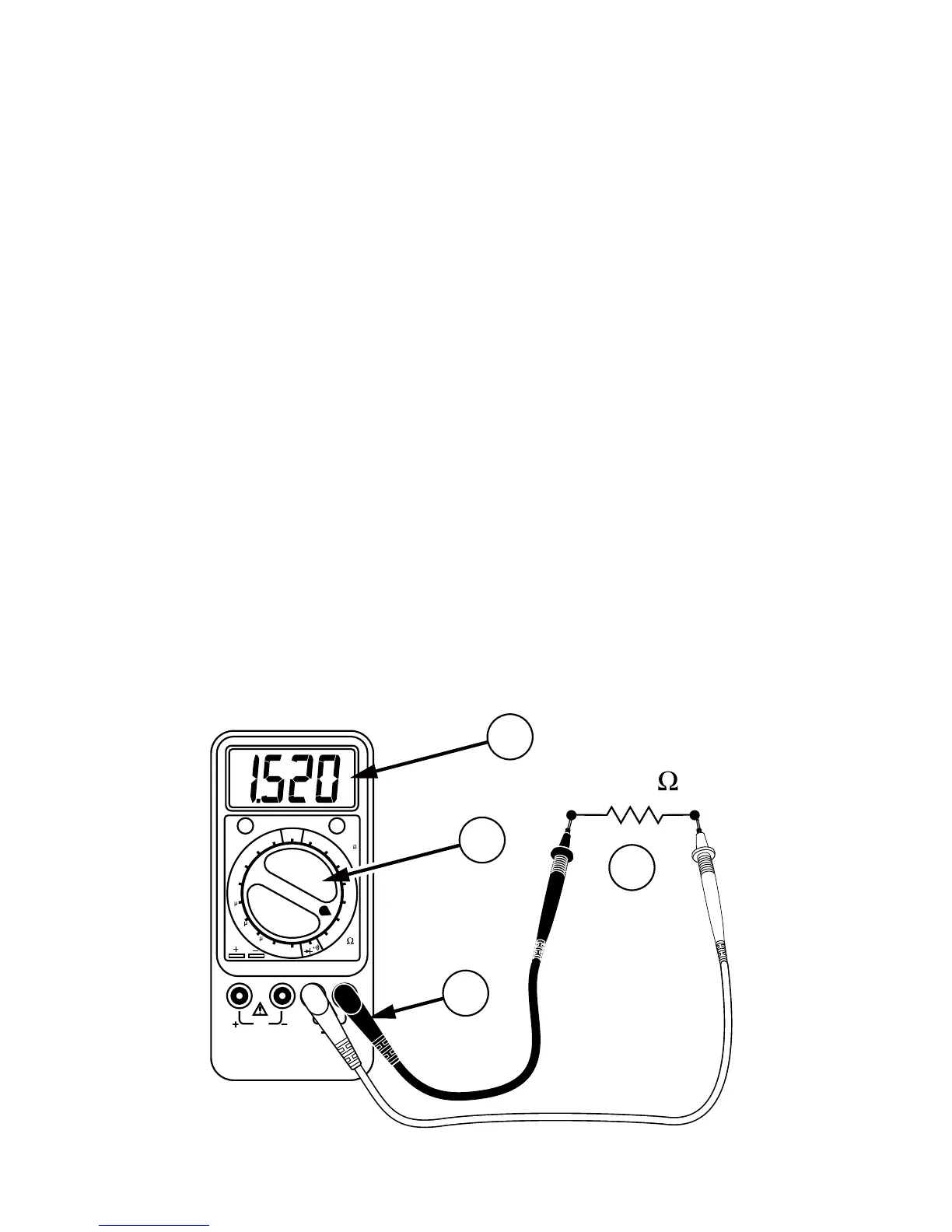
Resistance Measurement
1. Turn off power to the resistance to be
measured and discharge any capacitors.
Any voltage present during a resistance
measurement will cause inaccurate readings.
Connect red test lead to +Rx Input (red) and
black test lead to -Rx Input.
2. Set Function/Range Switch to the desired
Ω position.
3. Connect test leads to resistance or circuit to
be measured.
4. Read resistance value on Digital Display.
Open circuits will be displayed as an
overload condition.
Note: On the 20Ω range, an adjustment
potentiometer (ZERO ADJ.) allows you to zero
out the test lead resistance. Short the test leads
and adjust the knob until the display reads zero.
Cx
200
n
20m
200p
200
ZERO
ADJUST
(20 )
OFF
20
2k
2M
20M
CR50
F
20
k
200
k
2m
200
20
2
20n
2n
CAP.
ZERO
ADJUST
Rx
DISCHARGE CAPACITOR
BEFORE CONNECTING
1.520 k
4
3
2
1