5
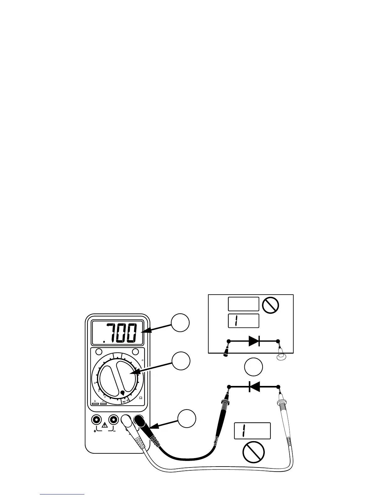
Diode and Transistor Test
1. Connect the red test lead to the +Rx Input
(red) and the black test lead to the –Rx Input.
2. Set the Function/range switch to
d
position.
3. Apply probe tip of red lead to the anode and
black lead to the cathode of the diode. The
meter’s display indicates the forward voltage
drop (approximately 0.7V for silicon diode or
0.4V for germanium diode). Meter will display
overload condition for an open diode.
4. Reverse test lead connections to the diode to
perform a reverse bias test. Overload indicates
a good diode.
Note: Overload condition for both reverse and
forward bias tests indicate an open diode. A
low voltage reading for both bias tests indicates
a shorted diode. If the diode is shunted by a
resistor of 1000 ohms or less, it must be removed
from the circuit before taking the measurement.
Bipolar transistor junctions may be tested in the
same manner described above.
Cx
200
n
20m
200p
200
ZERO
ADJUST
(20 )
OFF
20
2k
2M
20M
CR50
F
20
k
200
k
2m
200
20
2
20n
2n
CAP.
ZERO
ADJUST
Rx
DISCHARGE CAPACITOR
BEFORE CONNECTING
Cathode Anode
Cathode
600 - 900 mV
<1 V
Anode
4
3
2
1
OK
OK
OK
OK