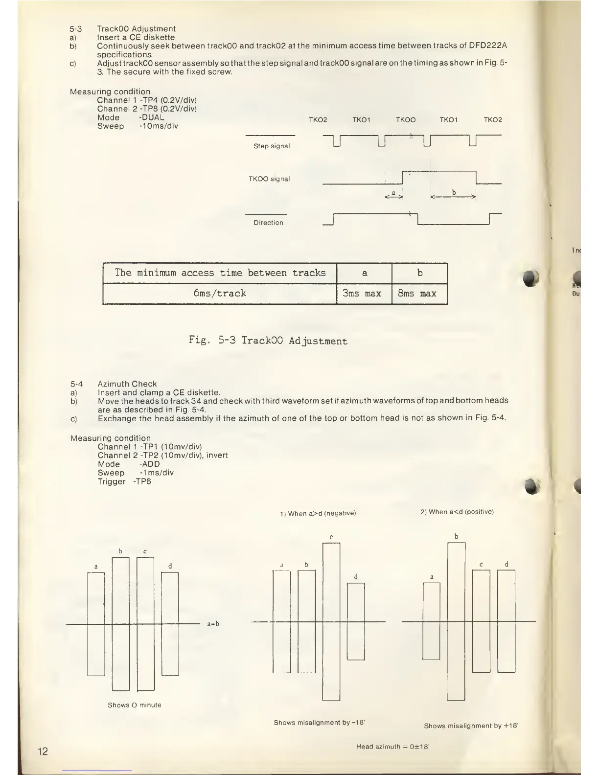
5-3
TrackOO Adjustment
a)
Insert
a
CE diskette
b)
Continuously seek between
trackOO and track02 at the
minimum
access
time between
tracks of DFD222A
specifications.
c)
Adjust
trackOO sensor assembly
so
that the step
signal and trackOO signal
are
on
the timing as shown
in Fig.
5-
3. The secure with the fixed screw.
Measuring
condition
Channel 1 -TP4 (0.2V/div)
Channel 2 -TP8 (0.2V/div)
Mode
-DUAL
Sweep
-10ms/div
TK02 TKOI TKOO TKOI TK02
Step
signal
~LT
u u U
TKOO signal
k
b
<-
*->
-*
rDirection
r
The minimum access time between
tracks a b
6ms/track
3ms max 8ms max
•
Fig.
5-3
TrackOO
Adjustment
5-4
Azimuth
Check
a)
Insert and
clamp
a
CE diskette.
b)
Move the
heads
to
track 34 and check
with third waveform set
if azimuth
waveforms of
top
and bottom
heads
are
as
described in Fig.
5-4.
c)
Exchange the
head assembly if the azimuth of
one of the top or
bottom head is not as
shown in Fig.
5-4.
Measuring condition
Channel 1 -TP1
(10mv/div)
Channel 2 -TP2
(10mv/div), invert
Mode
-ADD
Sweep
-1
ms/div
Trigger -TP6
*
1)
When
a>d
(negative)
2)
When
a<d
(positive)
b c
Shows O
minute
a
b
a=b
c d
Shows
misalignment
by
-18'
Shows
misalignment by
+18'
12
Head azimuth
=
0±18'