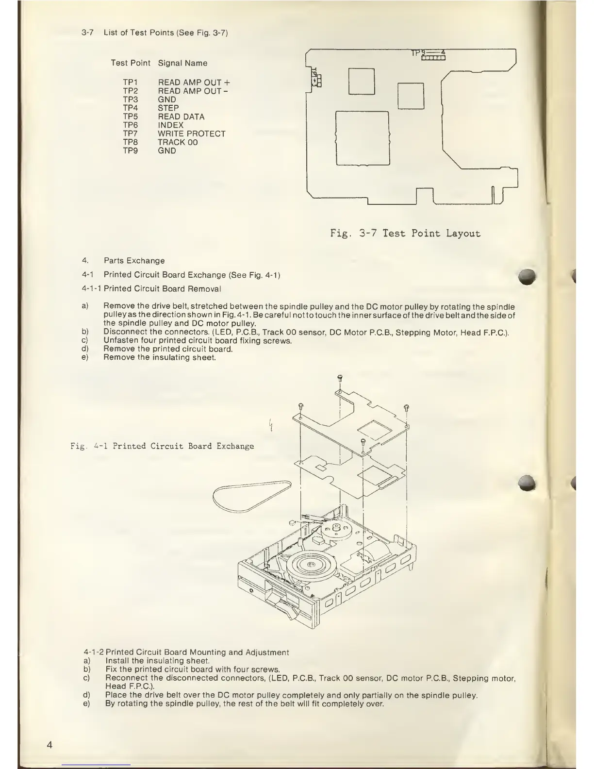
3-7
List of
Test Points
(See Fig. 3-7)
Test Point
Signal
Name r
TP
9-—
-4-
r
1
1 1 r
1
1
TP1
READ AMP
OUT
+
TP2
READ AMP
OUT
-
TP3
GND
TP4
STEP
TP5
READ DATA
TP6 INDEX
TP7 WRITE
PROTECT
TP8
TRACK
00
TP9
GND
I
Fig.
3-7
Test Point Layout
4.
Parts Exchange
4-1
Printed Circuit
Board
Exchange
(See Fig.
4-1)
4-1-1
Printed
Circuit
Board Removal
a)
b)
c)
d)
e)
Remove the
drive belt,
stretched
between the spindle
pulley and the
DC motor pulley
by
rotating
the spindle
pulley
as
the
direction shown
in Fig.
4-1.
Be careful
not to touch the inner surface
of the drive belt and
the side of
the
spindle pulley
and
DC motor pulley.
Disconnect the
connectors.
(LED,
P.C.B., Track
00 sensor, DC Motor P.C.B.,
Stepping Motor, Head
F.P.C.).
Unfasten four
printed circuit
board fixing
screws.
Remove the printed
circuit
board.
Remove the insulating
sheet.
Fig.
4-1
Printed
Circuit Board Exchange
*
4-1-2
Printed
Circuit Board
Mounting and Adjustment
a)
Install
the
insulating
sheet.
b)
Fix
the printed circuit board
with four screws.
c)
Reconnect
the disconnected
connectors,
(LED, P.C.B.,
Track
00
sensor,
DC motor P.C.B., Stepping
motor,
Head
F.P.C.).
d) Place the drive belt over
the DC motor pulley
completely and only
partially
on the spindle pulley.
e) By rotating the spindle pulley,
the rest of the belt will fit
completely over.