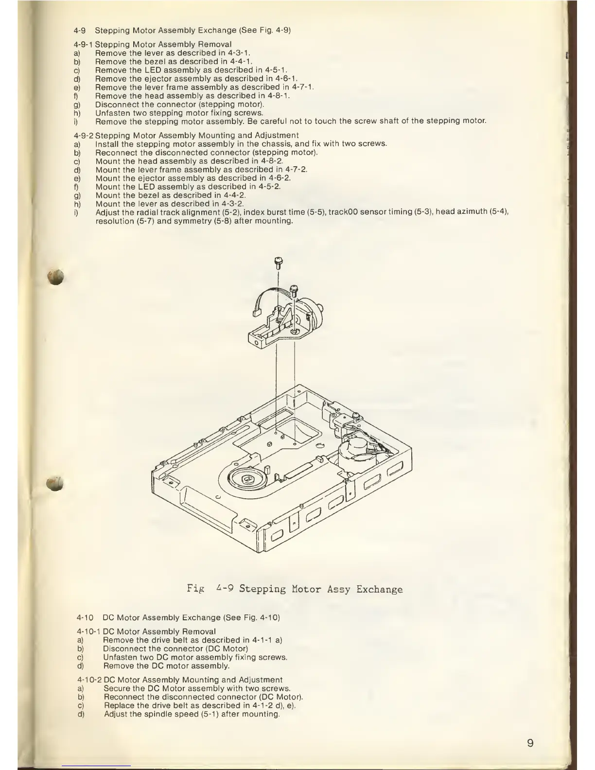
4-9
Stepping Motor
Assembly Exchange (See
Fig.
4-9)
4-9-1
Stepping
Motor Assembly Removal
a)
Remove the
lever
as
described in
4-3-1.
b)
Remove the bezel as
described in
4-4-1.
c)
Remove the LED
assembly
as
described
in
4-5-1.
d)
Remove the ejector
assembly
as
described
in
4-6-1.
e)
Remove the lever frame
assembly
as
described
in
4-7-1.
f)
Remove the head
assembly
as
described in
4-8-1.
g)
Disconnect the connector
(stepping motor).
h) Unfasten
two stepping motor
fixing screws.
i)
Remove the stepping
motor assembly. Be
careful not
to
touch
the screw
shaft of the
stepping motor.
4-9-2
Stepping Motor
Assembly Mounting
and Adjustment
a)
Install the
stepping motor assembly in
the chassis, and fix
with two
screws.
b)
Reconnect the
disconnected connector
(stepping motor).
c)
Mount the head
assembly
as
described
in
4-8-2.
d)
Mount the
lever frame assembly as
described in
4-7-2.
e)
Mount
the ejector assembly as
described in
4-6-2.
f) Mount
the LED assembly as
described in
4-5-2.
g)
Mount
the bezel as
described in
4-4-2.
h) Mount
the lever
as
described in
4-3-2.
i) Adjust the
radial track alignment (5-2),
index burst
time
(5-5),
trackOO sensor
timing
(5-3),
head
azimuth
(5-4),
resolution
(5-7)
and symmetry (5-8)
after mounting.
*
«tk
Fig
£-9
Stepping
Motor
Assy
Exchange
4-1
DC Motor Assembly Exchange (See
Fig.
4-1
0)
4-10-1
DC
Motor Assembly Removal
a) Remove the drive belt
as
described in
4-1-1
a)
b) Disconnect the connector
(DC
Motor)
c)
Unfasten two
DC
motor assembly fixing screws.
d)
Remove the
DC
motor assembly.
4-10-2
DC
Motor Assembly Mounting and Adjustment
a) Secure the
DC
Motor assembly with two screws.
b) Reconnect the disconnected connector (DC Motor).
c) Replace the drive belt
as
described in
4-1-2
d), e).
d) Adjust the spindle
speed
(5-1) after mounting.