CONTENTS
Technical Specification
Safety Tests
FD-3 Maintenance
Flow Charts
Hard Disc
Installation Instructions
Switch
Settings
Understanding
bad
sectors on
a
hard disc
Notes
Keyboard Exploded Diagram
Keyboard Control
PCB Layout
Keyboard Schematic Diagram
PC1640 Electrical Parts List
PC1
640/SD/DD/HD20
Cabinet Drawing
&
Parts
List
PC1640/SD/DD/HD20
CPU P.C. Board
PC1
640/SD/DD/HD20 CPU P.C. Board (Bottom View)
PC1640/SD/DD/HD20 Chassis Schematic Diagram
PC1
640/SD/DD/HD20
Chassis
Schematic Diagram
PC1640/SD/DD/HD20
Chassis Schematic Diagram
PC1640/SD/DD/HD20 Chassis Schematic Diagram
PC1640/SD/DD/HD20 Chassis
Schematic Diagram
PC1 640/SD/DD/HD20 Chassis Schematic Diagram
PC-MD Electrical Parts List
PC-MD Cabinet & Parts List
PC/MD Main/CRT/Volume P.C. Board
PC/MD Chassis Schematic Diagram
-
Power Supply
PC-MD Chassis Schematic Diagram
PC-MD Alignment
Instructions
PC-CD Electrical Parts List
PC-CD Electrical Parts List
PC-CD Alignment Instructions
PC/CD Chassis Schematic Diagram
•
PC/CD Chassis Schematic Diagram
PC/CD Main P.C. Board
PC/ECD Cabinet
&
Parts List
PC-ECD
Electrical Parts List
PC-ECD Alignment Instructions
PC-ECD RGB P.C. Board
PC/ECD CRT
P.C.
Board
PC-ECD Relay P.C. Board
PC/ECD Main P.C. Board
PC/ECD Chassis Schematic Diagram
PC/ECD
Chassis Schematic Diagram
-
PC/ECD Chassis Schematic Diagram
Monitor
Power Supply
Monitor
-TTL Decoder
Power
Supply
Monitor
Page
2
2
3-
14
15-
17
18
19
20
21 &22
23
24
24&25
26
27
28
29
30
31
32
33
34
35
35
36
37
38
39
40
40
41
41
42
43
44
45
46
47
48
48
48
49
50
51
52
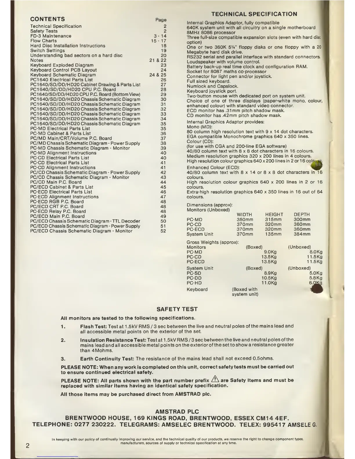
TECHNICAL SPECIFICATION
Internal
Graphics Adaptor, fully
compatible
640K system unit with all circuitry on a
single motherboard
8MHz
8086
processor
Three full-size compatible expansion slots (even with
hard disc
option)
One or two 360K 5'A" floppy disks or one
floppy with
a
20
Megabyte hard disk drive.
RS232
serial and parallel
interface
with standard connectors.
Loudspeaker with volume control.
Battery back-up real time clock and configuration RAM.
Socket for
8087
maths
co-processor
Connector
for light
pen
and/or joystick.
Full sized keyboard.
Numlock and Capslock.
Keyboard joystick port.
Two-button mouse with dedicated port on system unit.
Choice of one of three displays (paper-white mono, colour,
enhanced
colour) with standard video connector.
ECD monitor has
.31 mm pitch shadow mask.
CD
monitor has .42mm pitch
shadow mask.
Internal Graphics
Adaptor provides:
Mono(MD):
80
column high resolution text with 9x14 dot
characters.
EGA compatible
Monochrome graphics 640 x 350
lines.
Colour (CD):
(for use with CGA and
200-line EGA software)
40/80
column text with 8x8 dot
characters in 1
6
colours.
Medium resolution
graphics
320
x
200
lines in 4 colours.
High resolution colour graphics 640 x 200
lines in 2 or 1
6
col^
Enhanced Colour (ECD):
40/80
column text with 8 x 14 or 8 x 8 dot
characters in 16
colours.
High resolution colour
graphics 640 x 200 lines in 2 or 16
colours.
Extra-high
resolution graphics 640 x
350
lines in 16 out of 64
colours.
oIum^
Dimensions (approx):
Monitors
(Unboxed)
PC-MD
PC-CD
PC-ECD
System Unit
Gross Weights
(approx):
Monitors
PC-MD
PC-CD
PC-ECD
System Unit
PC-SD
PC-DD
PC-HD
WIDTH
350mm
370mm
370mm
370mm
HEIGHT
315mm
320mm
320mm
135mm
(Boxed)
9.0Kg
13.5 Kg
13.5 Kg
DEPTH
300mm
360mm
360mm
384mm
(Unboxed)
8.0Kg
11.5Kg
11.5Kg
(Boxed)
(Unboxed)
8.9Kg
10.5 Kg
11.0Kg
Keyboard
(Boxed with
system
unit)
5.0Kg
5.
8 Kg
e^QKg
SAFETY TEST
All monitors are tested to
the following
specifications.
1 . Flash Test: Test at 1
.5kV RMS
/
3 sec
between the live
and neutral poles
of the mains lead
and
all accessible metal
points on the exterior of
the
set.
2. Insulation
Resistance Test: Test at 1
.5kV RMS
/
3 sec
between the live
and neutral poles
of the
mains lead and
all accessible metal points
on the
exterior of the set to
show
a
resistance
greater
than 4Mohms.
3. Earth Continuity
Test: The resistance
of the mains
lead shall not
exceed 0.5ohms.
PLEASE NOTE: When any
work is completed
on this unit,
correct safety tests
must
be
carried
out
to
ensure continued
electrical safety.
PLEASE
NOTE: All parts
shown with the part
number prefix
/'\
are Safety Items
and must be
replaced
with similar items having
an identical safety
specification.
All those items may be
purchased direct from
AMSTRAD pic.
AMSTRAD PLC
BRENTWOOD HOUSE,
169 KINGS
ROAD, BRENTWOOD, ESSEX CM14
4EF.
TELEPHONE: 0277
230222.
TELEGRAMS: AMSELEC
BRENTWOOD. TELEX: 995417
AMSELE G.
In keeping with our
policy of continually improving our service, and the
technical quality of our products, we reserve
the right
to
change component types,
manufacturers, sources
of
supply
or
technical specification at any
time.