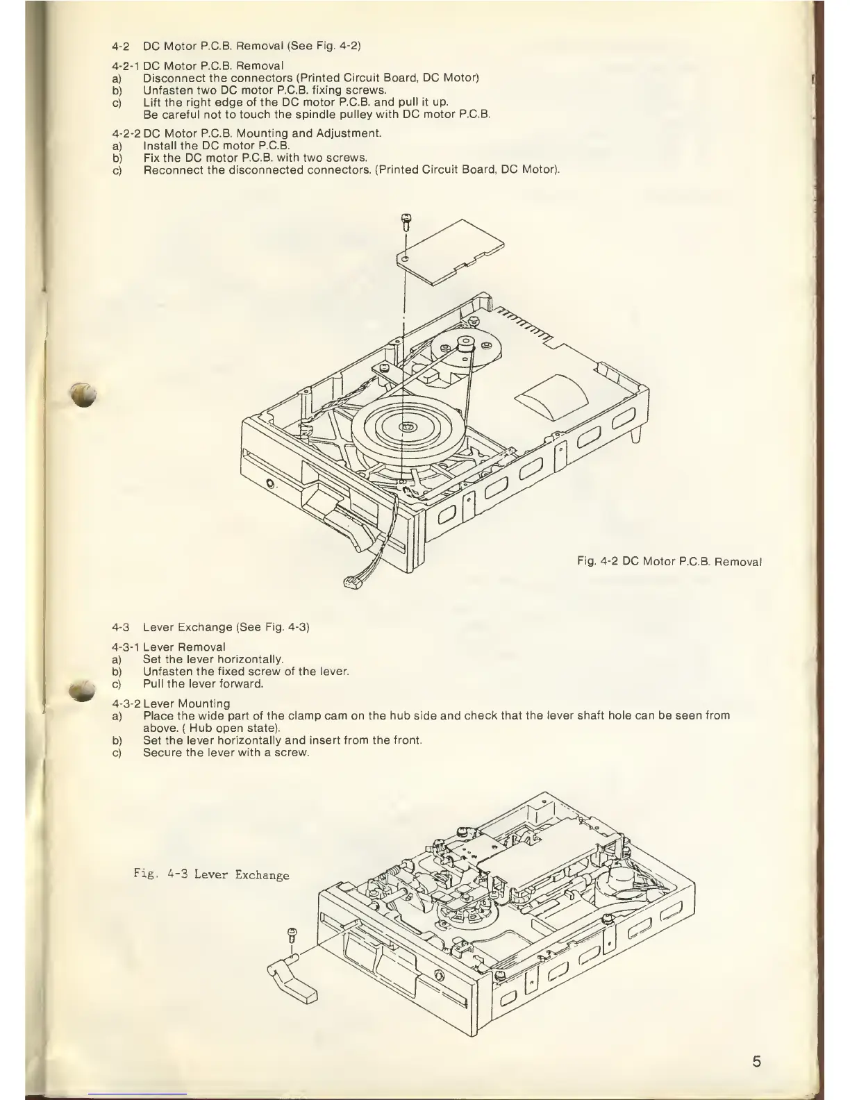
4-2
DC
Motor P.C.B.
Removal (See Fig.
4-2)
4-2-1
DC
Motor P.C.B.
Removal
a)
Disconnect
the connectors
(Printed Circuit Board, DC
Motor)
b)
Unfasten
two DC
motor P.C.B. fixing screws.
c)
Lift the right edge
of the
DC
motor P.C.B. and
pull it
up.
Be
careful
not
to
touch the spindle pulley
with
DC
motor P.C.B.
4-2-2
DC
Motor P.C.B.
Mounting and Adjustment.
a)
Install the DC
motor P.C.B.
b)
Fix the DC
motor P.C.B. with two screws.
c)
Reconnect
the disconnected
connectors. (Printed Circuit
Board, DC
Motor).
Fig.
4-2
DC
Motor P.C.B.
Removal
4-3
Lever Exchange (See
Fig.
4-3)
4-3-1
Lever Removal
a) Set
the lever horizontally.
b)
Unfasten the fixed screw of the lever.
c)
Pull the lever forward.
4-3-2
Lever Mounting
a)
Place the wide
part of the clamp cam on the hub side and
check that the lever shaft hole can be seen from
above.
(
Hub
open
state).
b)
Set the lever
horizontally
and
insert from the front.
c)
Secure the lever
with
a
screw.
Fig. 4-3
Lever
Exchange