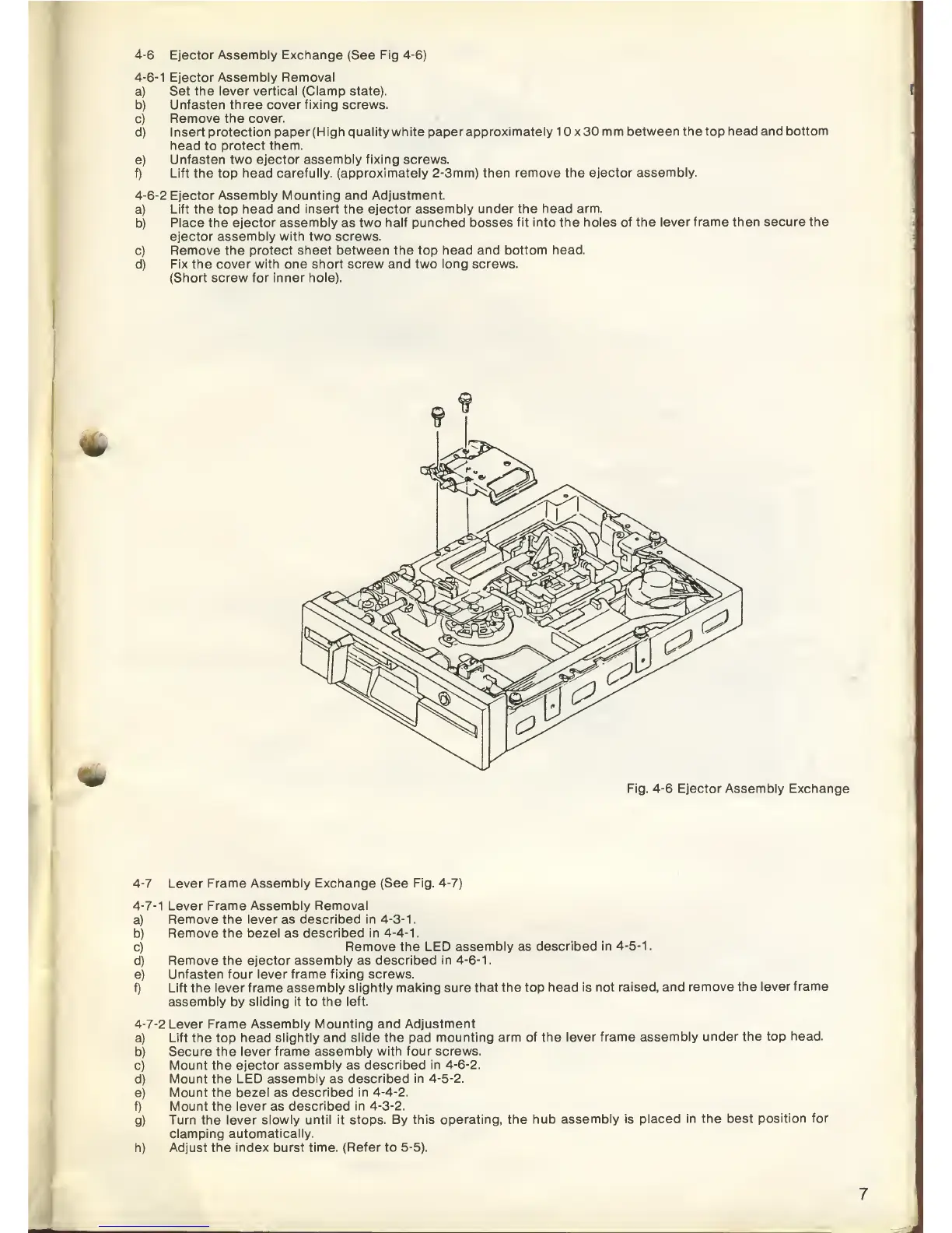
4-6
Ejector Assembly Exchange (See Fig
4-6)
4-6-1
Ejector Assembly Removal
a) Set
the lever vertical (Clamp
state).
b)
Unfasten three cover fixing screws.
c)
Remove the cover.
d)
Insert protection paper (High quality
white paper approximately 10x30
mm between the top
head and bottom
head to protect
them.
e)
Unfasten two ejector assembly fixing screws.
f)
Lift
the
top
head carefully, (approximately
2-3mm) then remove the
ejector assembly.
4-6-2
Ejector
Assembly Mounting and Adjustment.
a)
Lift
the
top
head and insert the ejector assembly
under the head arm.
b)
Place the ejector assembly
as
two half punched bosses
fit into the holes
of the lever frame then
secure the
ejector assembly with two screws.
c)
Remove the protect
sheet between the
top
head and bottom head.
d)
Fix the cover
with one short screw and two long screws.
(Short
screw for inner hole).
m
AMI
Fig.
4-6
Ejector
Assembly
Exchange
4-7
Lever Frame Assembly Exchange (See
Fig.
4-7)
4-7-1
Lever Frame Assembly Removal
a)
Remove the
lever
as
described in
4-3-1
.
b)
Remove the bezel as
described
in
4-4-1.
c)
Remove the LED assembly as
described
in
4-5-1
.
d)
Remove the
ejector assembly
as
described in
4-6-1
.
e)
Unfasten four lever
frame fixing screws.
f) Lift the lever frame
assembly slightly making sure that
the
top
head is
not raised, and
remove the
lever frame
assembly by
sliding it
to
the left.
4-7-2
Lever Frame
Assembly Mounting and Adjustment
a)
Lift the top head
slightly and slide the pad
mounting arm of the
lever frame assembly
under the top
head.
b)
Secure the lever
frame assembly with four screws.
c)
Mount the ejector
assembly
as
described in
4-6-2.
d)
Mount the LED
assembly
as
described in
4-5-2.
e)
Mount the
bezel
as
described in
4-4-2.
f) Mount the
lever
as
described in
4-3-2.
g)
Turn
the lever slowly until it stops. By
this operating, the hub
assembly is
placed in the best
position for
clamping automatically.
h) Adjust the index burst time.
(Refer
to
5-5).