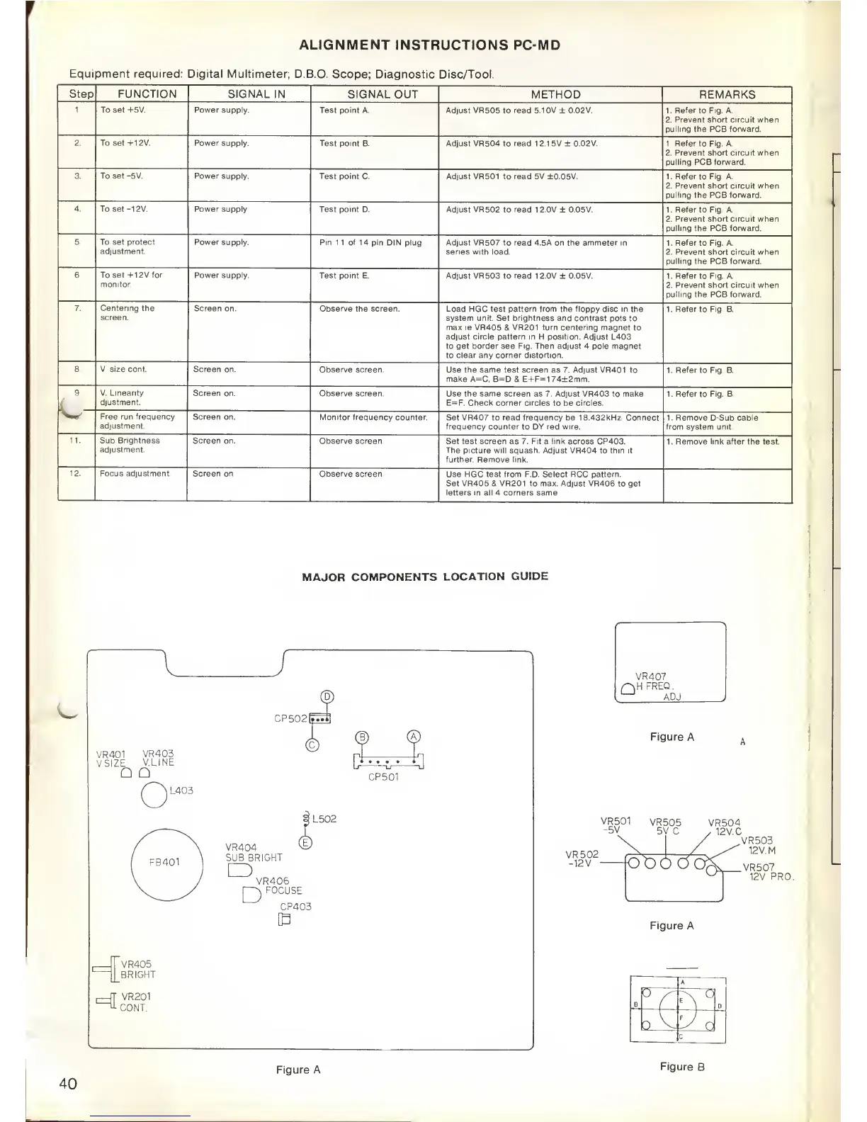
ALIGNMENT
INSTRUCTIONS PC-MD
Equi pment required: Digital Multimeter;
D.B.O.
Scope;
Diagnostic
Disc/Tool.
Step
FUNCTION
SIGNAL
IN SIGNAL OUT
METHOD REMARKS
1. To
set +5V.
Power supply.
Test
point A. Adjust VR505 to read 5.10V ± 0.02V. 1. Refer
to
Fig. A.
2. Prevent short circuit when
pulling the PCB forward.
2.
To set +12V. Power supply.
Test point B. Adjust
VR504 to
read
1
2.1
5V ± 0.02V. 1. Refer to Fig. A.
2. Prevent short circuit
when
pulling PCB forward.
3. To set -5V. Power supply.
Test point
C
Adjust VR501
to
read
5V ±0.05V. 1. Refer to Fig. A.
2. Prevent short circuit when
pulling the
PCB forward.
4. To set -12V. Power
supply Test point
D. Adjust VR502 to read 1 2.0V ±
0.05V.
1. Refer
to Fig. A.
2. Prevent short circuit when
pulling the PCB forward.
5. To
set protect
adjustment.
Power supply. Pin
11 of 14 pin DIN plug. Adjust
VR507 to read 4.5A on the ammeter in
series with load.
1. Refer
to
Fig. A.
2. Prevent short circuit when
pulling the PCB forward.
6. To set +12V for
monitor.
Power
supply. Test point
E. Adjust VR503 to read 1 2.0V
+
0.05V. 1. Refer
to Fig. A.
2. Prevent short circuit
when
pulling the PCB forward.
7. Centering
the
screen.
Screen on.
Observe the screen.
Load HGC test pattern from the floppy disc in the
system unit. Set brightness and contrast pots
to
max
ie
VR405 & VR201 turn centering magnet to
adjust
circle
pattern in H position. Adjust L403
to get
border
see Fig. Then adjust 4 pole magnet
to clear any
corner
distortion.
1. Refer
to
Fig.
B.
8. V. size cont. Screen
on. Observe screen.
Use
the same test screen
as 7.
Adjust
VR401 to
make A=C.
B=D & E+F=1
74±2mm.
1. Refer
to
Fig.
B.
9.
L
V. Linearity
djustment.
Screen on.
Observe screen.
Use the same screen
as
7. Adjust
VR403 to make
E=F. Check corner circles to be circles.
1. Refer to Fig. B.
V*
Free run frequency
adjustment.
Screen on.
Monitor
frequency counter.
Set
VR407
to
read frequency
be 18.432kHz. Connect
frequency counter to DY red wire.
1. Remove D-Sub cable
from
system
unit.
11. Sub Brightness
adjustment.
Screen on.
Observe screen.
Set test
screen
as 7. Fit a
link
across CP403.
The picture will squash. Adjust VR404
to thin it
further. Remove link.
1. Remove link after the
test.
12.
Focus
adjustment.
Screen on.
Observe screen.
Use HGC test from F.D. Select RCC pattern.
Set VR405 & VR201 to max. Adjust VR406 to get
letters in all 4 corners same.
MAJOR
COMPONENTS
LOCATION
GUIDE
VR401
VR403
VSIZE
V.LINE
CP502lfin
/^~^L403
CP501
VR405
BRIGHT
i
—
r
r
VR201
CONT.
L502
VR404
vE
SUB BRIGHT
D
VR406
FOCUSE
D
CP403
Figure A
VR501
VR505
VR504
-5V
5V.C
,
12
V.
C
VR502
-12V
-
foo6d
Figure
A
VR503
12V. M
>(-
>,
VR507
12V.
PRO.
A
I
B
v
^
n
cY
P
o
c
40
Figure A
Figure
B