AXB-F117 Stealth 1 Camera Controller Installation 19
Data and power
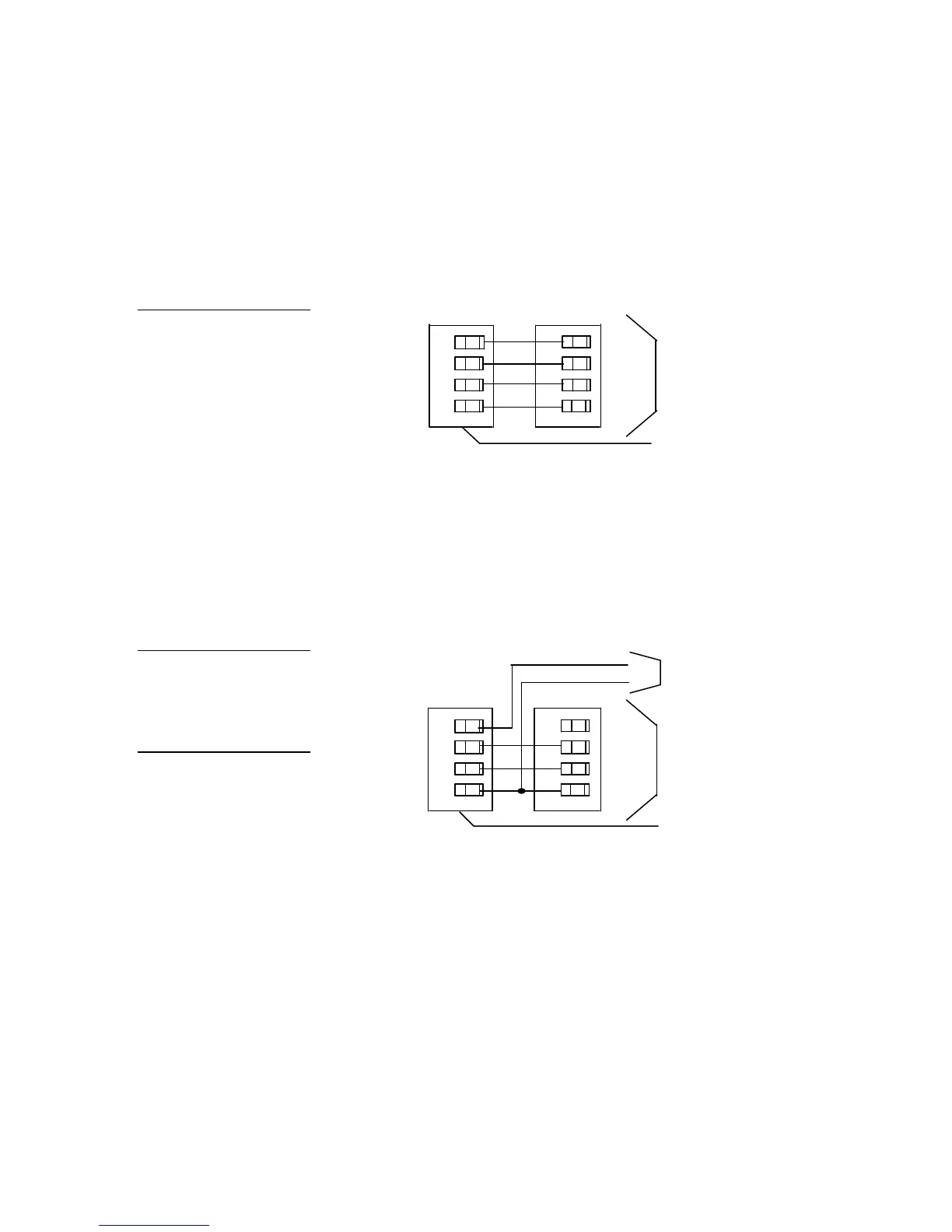
To use the AXlink connector for data and power, connect the AMX Control
System’s AXlink connector to the AXlink connector on the rear panel, as shown in
Figure 22.
AXB-F117 AXlink connector
Data and local 12 VDC power supply
To use the AXlink 4-pin connector for data with a local 12 VDC power supply,
connect the AMX Control System’s AXlink connector to the AXlink connector, as
shown in Figure 23.
AXB-F117 AXlink connector
Local 12 VDC power supply
Use the local 12 VDC power supply when the distance between the AMX Control
System and AXB-F117 exceeds the limits listed in Figure 21. Make sure to connect
only the GND wire on the AXlink/RS-232 connector when using a local 12 VDC
power supply. Do not connect the PWR wire to the AXlink connector’s PWR
terminal.
Figure 22
AXlink 4-pin connector wiring
diagram for power and data
Figure 23
AXlink connector and local 12
VDC power supply wiring
Caution
Do not connect the wire from
the PWR terminal on the
AXCESS Control System to
the PWR terminal on the
AXB-F117 when you connect
an external power supply.
 Loading...