22 Installation AXB-F117 Stealth 1 Camera Controller
Servomotor-driven outputs are intended to drive servo-type motors only! The
outputs have very low current (milliamp range) capability. DO NOT attempt to
drive conventional motors with these outputs or you will damage the output
drivers. If you are not sure about the motor type, refer to the Technical Support
section and contact AMX Corporation for assistance.
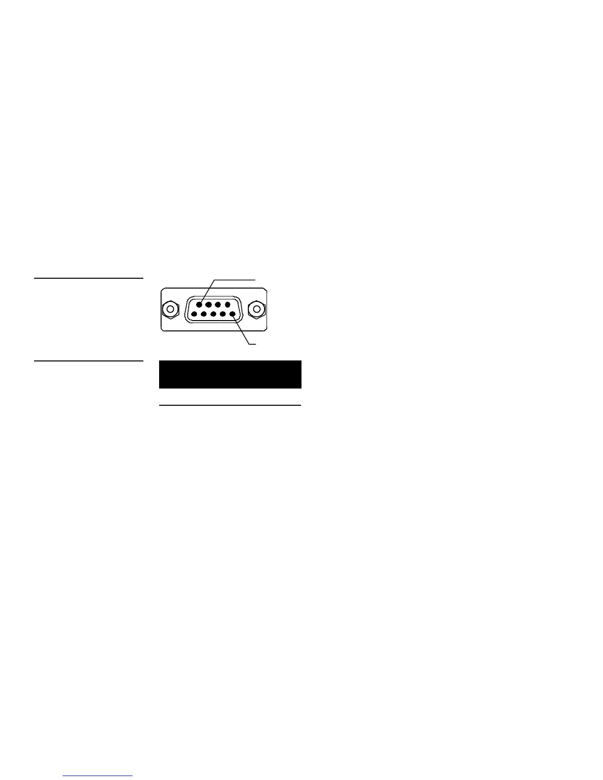
Using the camera control RS-232 DB-9 connector
Connect the AXB-F117 RS-232 DB-9 (male) connector to the camera head’s RS-232
connector. Figure 28 shows the DB-9 connector and Figure 29 lists the pinouts.
Camera control DB-9
RS-232 connector pinouts
Pin Signal Pin Signal
1
2
3
4
5
N/A
RXD
TXD
NA
GND
6
7
8
9
N/A
RTS
CTS
N/A
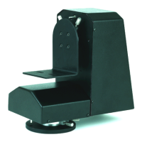
Setting the adjustable pan-limit stops
To set the adjustable pan-limit stops:
1. Ensure that there is enough slack in the lens, camera, and AXB-F117 AXlink
cables to accommodate the full range of pan/tilt motion.
2. Loosen the adjustable pan-limit stops shown in Figure 30.
3. Using the control panel, pan the AXB-F117 to the right until you reach the
desired right pan-limit position.
4. Locate the adjustable pan-limit stop on the left side of the AXB-F117, and move
it until it makes contact with the pan-limit switch.
Figure 28
RS-232 camera control DB-9
Figure 29
Camera control RS-232 DB-9
connector pinouts
 Loading...