20 Installation AXB-F117 Stealth 1 Camera Controller
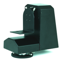
External RS-232 control device or PC
To use the AXlink 4-pin connector with an external RS-232 control device or PC,
connect the AXlink connector to the RS-232 DB-9 connector as shown in Figure 24.
Connector pins 2, 3, and 5 are used for data and ground. For some applications
that require hardware handshaking, you may need to strap pins 7 (request to send)
and 8 (clear to send) together.
Local 12 VDC
AXB-F117 AXlink
Optional 7-to-8
External RS-232 DB-9
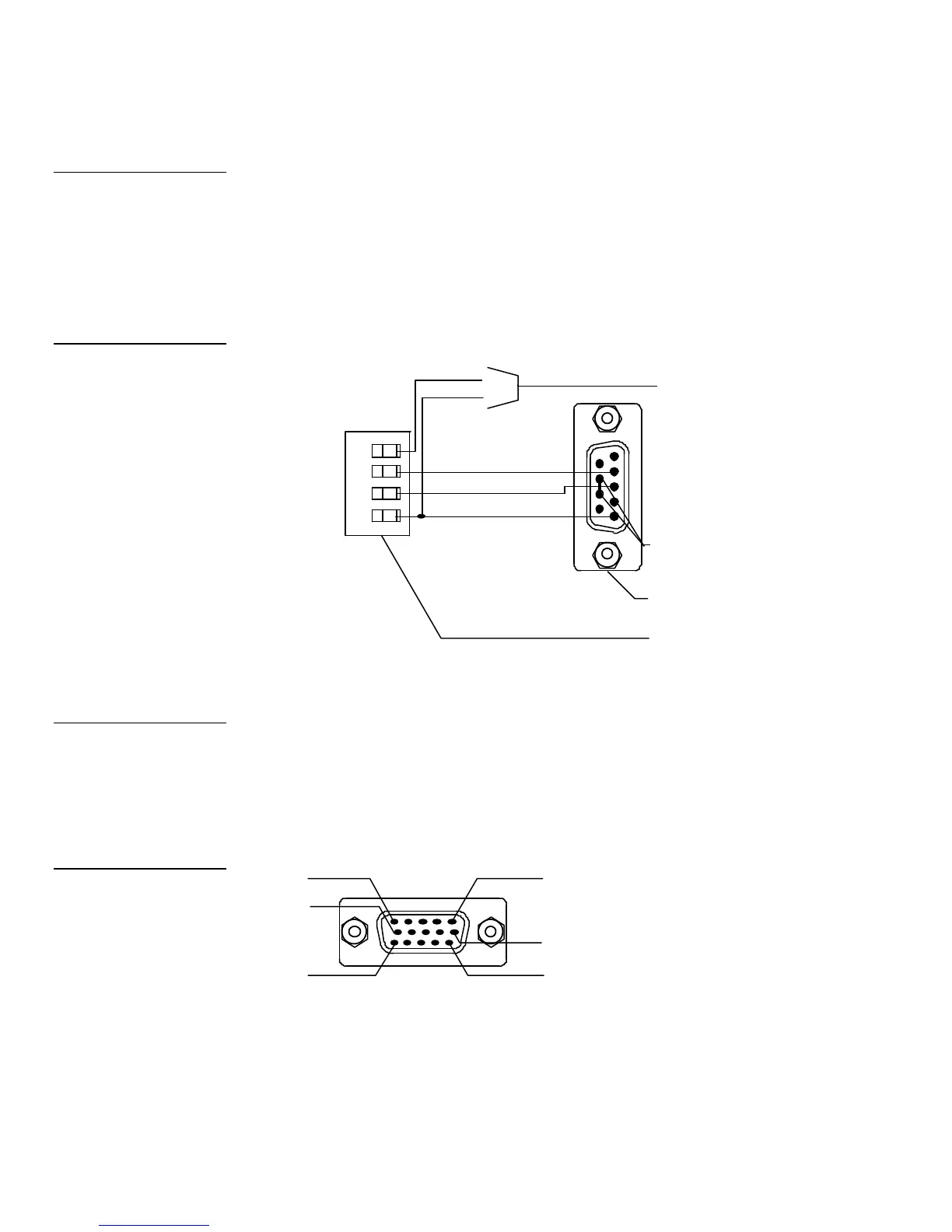
Using the lens control DB-15 HD (high density) connector
The AXB-F117 is designed to control servomotor mode and motor-mode camera
lenses. Refer to the Pre-Installation Settings section to set the lens switches for
servomotor mode or motor mode. Figure 25 shows the DB-15 HD connector pin
numbers, Figure 26 lists the pinouts for motor-mode lenses, and Figure 27 lists the
pinouts for servomotor-mode camera lenses.
Note
To use a PC, set the internal
jumpers for RS-232
communication mode and the
Device DIP S2 switch
positions 1 through 8 off
Figure 24
External RS-232 control
device or PC wiring diagram
Note
If you build your own cable,
acquire the lens interface
connector from the
appropriate lens
Figure 25
Lens control DB-15 HD
connector (female) wiring
 Loading...