7-1 Introduction Waveguide Adapter Kit Instructions
7-2 PN: 10410-00311 Rev. F VectorStar ME7838x/x4 Modules RM
Index Description
Part
Number Index Description
Part
Number
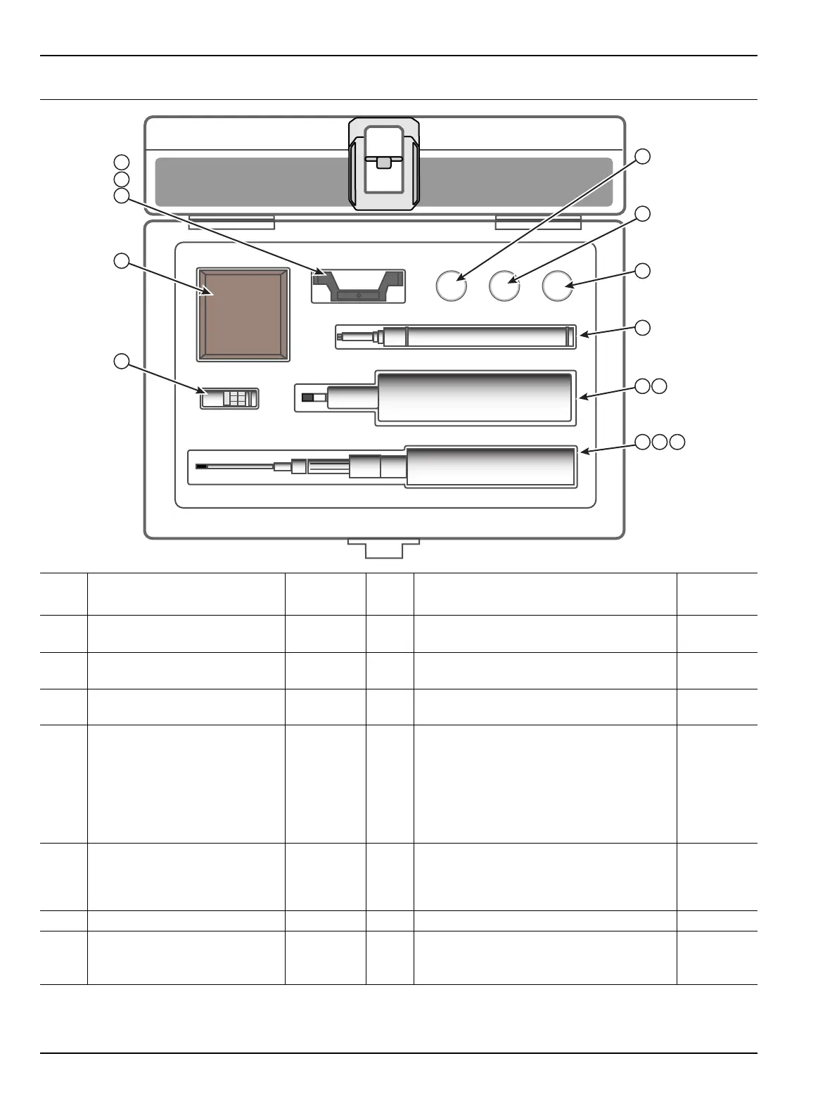
1
Hex Torque Driver 0.042 N·m
(6 ozf·in)
01-520 5
Waveguide flange socket head screws
(small metric head), 4-40 x 7 mm long
3-900-945
1a Hex Insert Pin Chuck 01-521 6
Waveguide flange socket head screws,
4-40 x 5/16 in long
900-562
1b Hex Bit (0.035 in) 01-522 7
Socket Head Screw (installed on bracket
(item 9)), M3 x 9 mm long
3-74212
2
Hex Torque Driver 0.564 N·m
(5 lbf·in)
01-519 8
a
a. Items 8, 9, and 10 ship already attached to the mmW module, so are not included in the Waveguide Accessory Kit.
Waveguide to coax adapter – WR-10
(W band system only)
Waveguide to coax adapter – WR-12
(E band system only)
Waveguide to coax adapter – WR-15
(V band system only)
3-1091-400
3-1091-401
3-1091-402
2a 01-523 Hex Bit (2.5 mm) 01-523 9
a
Adapter Bracket (W band)
Adapter Bracket (E band)
Adapter Bracket (V band)
3-74057-1
3-74057-2
3-74057-3
3 Hex wrench, metric, 2 mm 74640 10
a
V Termination V210
4
Set Screws M2 x 3 mm long
(quantity 3 installed on bracket
(9) + quantity 3 spares in vial)
3-905-2779
Figure 7-2. Waveguide Accessory Kit Contents