3744x-EE/EW mm-Wave Module 5-2 3744x-EE/EW mm-Wave Module and Bracket
VectorStar ME7838x/x4 Modules RM PN: 10410-00311 Rev. F 5-3
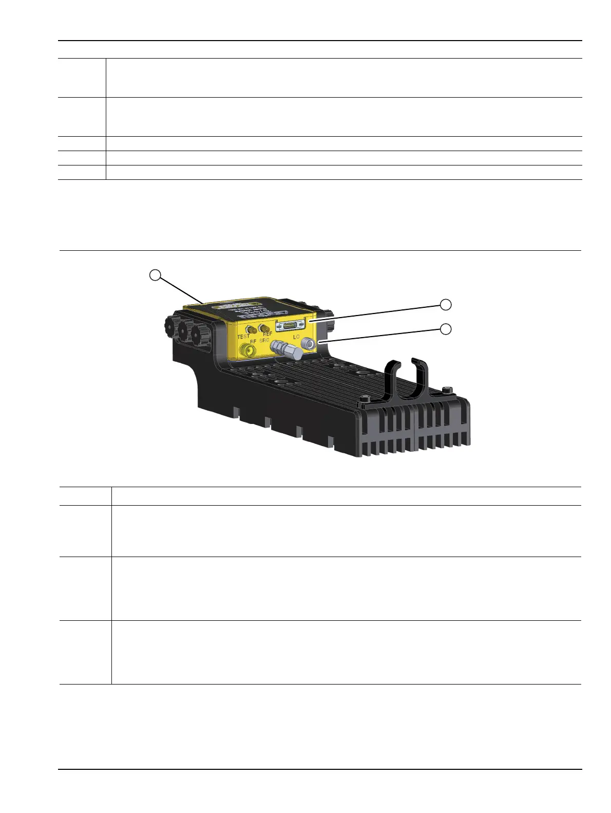
Alternate Mounting Configuration
If required, the module can be turned over for different connector elevation as shown below in Figure 5-2.
9 REF SSMC Connector
• To tighten, use a 4 mm (5/32”) torque end wrench set to less than 0.17 N·m (1.5 lbf·in).
• Recommended is Anritsu 01-529-R torque wrench.
10 TEST SSMC Connector
• To tighten, use a 4 mm (5/32”) torque end wrench set to less than 0.17 N·m (1.5 lbf·in).
• Recommended is Anritsu 01-529-R torque wrench.
11 Power/Signal Latching Bi-Lobe™ Connector
12 Factory Calibrated Port Assignment Label
13 Module Serial Number Label
Index Description
1 The module can be placed in an alternate position by removing the Knurled Thumbscrews and turning
the module upside down.
• In this orientation, the W (1mm) connector is farthest from the bottom of the bracket.
•The W (1mm) connector is on the same plane as the SRC connector.
2 Connect the bottom row of connectors first, from middle to right side, and then left side, using torque
factors described above:
• REF
• TEST
• Power/Signal
3 Connect the top row of connectors last, from middle to right side, then left side, using torque factors
described above:
• SRC
• RF
• LO
Figure 5-2. 3744A/E-xx Millimeter-Wave Module – In Bracket – Alternate Module Orientation
Figure 5-1. Millimeter-Wave 3744A/E-xx Module Description (2 of 2)