VectorStar ME7838x/x4 Modules RM PN: 10410-00311 Rev. F 2-1
Chapter 2 — MA25400A mm-Wave Module
2-1 Introduction
This chapter provides a description of the MA25400A Millimeter-Wave (mm-Wave or as labeled, mmW)
Module. The MA25400A Module is used with the VectorStar ME7838 Series Broadband/Millimeter-Wave
(BB/mm-Wave) VNA System.
When the ME7838 system is ordered, the typical configuration provides a 3739C Broadband Test Set and two
mm-Wave modules to be used with the VNA. Each module is characterized for a specific VNA Serial Number
and a specific VNA Test Port. Additional information for heat sinking and user-defined mounting is given in
Chapter 8. Complete installation documentation is in the applicable VectorStar ME7838 Series System
Installation Guide. Refer to Section 1-3 “Related Documentation” on page 1-2 for the document part number.
2-2 MA25400A mm-Wave Module and Bracket
MA25400A Module Installation
The flange interface is based on a standard UG-387 waveguide flange and one connects to it by first lining up
the alignment pins and then mating the flanges.
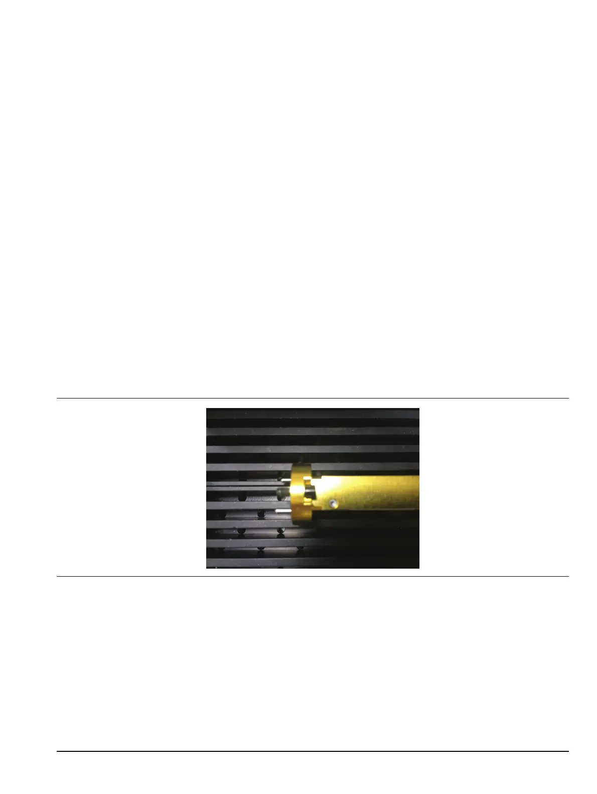
Standard captive waveguide screws are used with an exposed shank. This is useful since both mating flanges
may have threaded holes. Thread the screws all the way into the mating flange (so the shank clears) before
mating to the module. This simplifies assembly and avoids cross-threading.
Use a 6 N-cm torque wrench for these screws (one is in the accessory kit). Tighten in a star pattern (or slowly
tighten opposite sides sequentially when using two screws).
Figure 2-1. Waveguide Screw Threaded Through the Flange