3744x-Rx Receiver Module 6-2 3744x-Rx Millimeter-Wave Module and Bracket
VectorStar ME7838x/x4 Modules RM PN: 10410-00311 Rev. F 6-3
Alternate Mounting Configuration
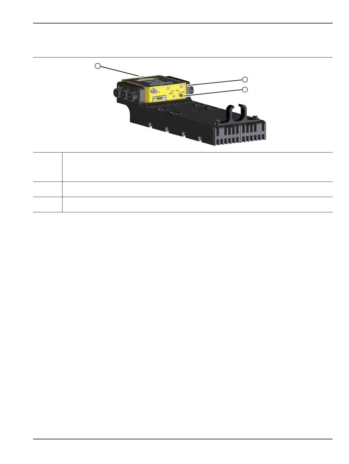
If required, the module can be turned over for different W connector elevation as shown below in Figure 6-2.
1
1 – The module can be placed in an alternate position by removing the Knurled Thumbscrews and
turning the module upside down.
• In this orientation, the W (1mm) connector is farthest from the bottom of the bracket.
•The W (1mm) connector is opposite the SRC connector.
2
2 – Connect the bottom row of connectors first, using torque factors described above:
• TEST; REF (No Connection); Power/Signal
3
3 – Connect the top row of connectors last, using torque factors described above:
• LO; SRC (No Connection); RF (No Connection)
Figure 6-2. 3744A/E-Rx Millimeter-Wave Module – In Bracket – Alternate Module Orientation