7-3 Two-Port Alignment Waveguide Adapter Kit Instructions
7-6 PN: 10410-00311 Rev. F VectorStar ME7838x/x4 Modules RM
7-3 Two-Port Alignment
1. Prepare Port 1 for alignment by loosening the six Thumb Screws (Item 13) a small amount.
See Figure 7-7.
2. Prepare Port 2 for alignment by loosening the W Nut, the three Set Screws (Item 4), and the six Thumb
Screws (Item 13) a small amount.
3. Place the 2 units with the heat sinks resting on a flat surface and the waveguide test ports facing each
other. Carefully align the waveguide ports and slide the units together so that ports 1 and 2 are
connected. A DUT can be inserted if desired as shown in Figure 7-8.
4. Tighten the Port 2 W Nut with the 0.45 N· m (4 lbf· in) Torque Wrench while holding the waveguide
flange to prevent it from rotating. Check that the two waveguide test ports can be disconnected and
reconnected without binding.
If the waveguide alignment pins do not insert smoothly into the alignment holes, loosen the W Nut and
repeat steps 3 and 4.
5. With the waveguide ports connected, evenly tighten the two set screws (Item 4) of Port 2 with the Hex
Torque Driver (Item 1) (6 ozf.in).
Check that the waveguide test ports can still be disconnected and reconnected without binding.
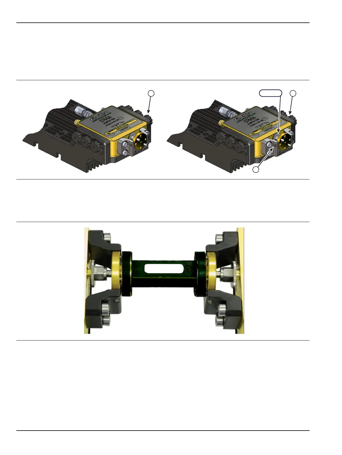
Figure 7-7. Port 1 and Port 2 Alignment
Figure 7-8. Two Port Alignment with DUT
4
13
13
3X
6X 6X
W1 Nut
Port 1 Port 2
4.