Waveguide Adapter Kit Instructions 7-2 Adapter Installation
VectorStar ME7838x/x4 Modules RM PN: 10410-00311 Rev. F 7-5
5. Slide the Adapter Mounting Bracket semi-circular opening over the Waveguide to Coax Adapter (Item 8)
and align four captivated Socket Head Screws (Item 7) to the four holes of the 3744x mmW module
(Item 11).
6. Carefully tighten the four Socket Head Screws to the 3744x Module using the Hex Torque Driver,
(Item 2) - 0.56 N· m (5 lbf· in). Do not over tighten.
7. If the waveguide aperture is not in the desired orientation, loosen the W (1mm) connection and rotate the
waveguide adapter.
Re-tighten the W connector using the Torque Wrench while holding the flange in position.
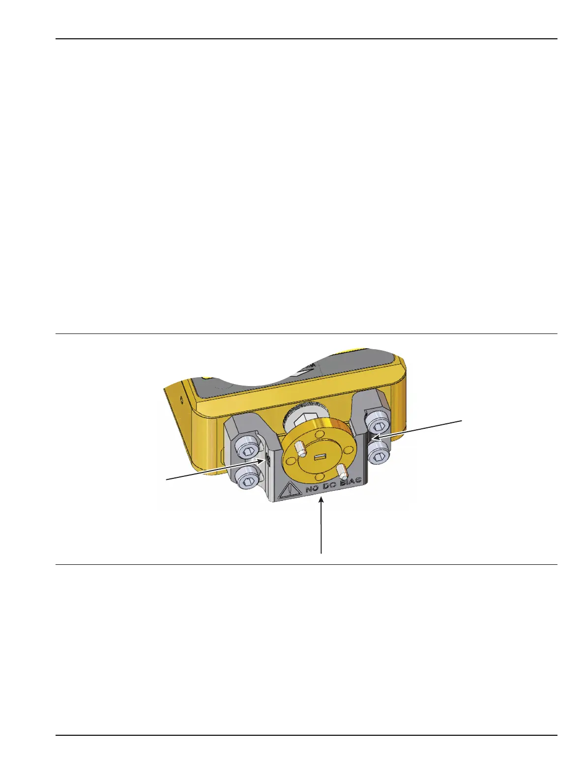
8. Secure the waveguide adapter in place by tightening the three set screws (Item 4) in the Adapter
Mounting Bracket shown in Figure 7-6. This requires the following sequence for both tightening and
loosening using the Hex Torque Driver, (Item 1) - 0.042 N· m (6 ozf· in).
a. The left and right side set screws shown with arrows in the figure should be tightened first.
Alternating between the left and right screws, tighten both set screws evenly until the flat point of
each set screw is just touching the Waveguide Adapter flange.
b. Proceed left then right with short even turns on both set screws until the Hex Torque driver
reaches its 6 ozf· in torque limit.
c. After the left and right set screws are torqued, adjust the bottom set screw (shown with a vertical
arrow in Figure 7-6) until it just touches the Waveguide to Coax Adapter (Item 8) flange.
Do not torque the bottom set screw. Leave it just touching the waveguide adapter flange.
9. Connect the V Termination (Item 10) to the “SRC” connector of the 3744x mmW Module. Tighten the
termination using the Torque Wrench, (Item 14) - 0.90 N· m (8 lbf· in).
10. Installation is complete. For a 2 port system repeat Steps 1 through 9 for the second module, then proceed
to Section 7-3 for two-port alignment instructions.
Figure 7-6. Set Screw Tightening
Left
Right
Bottom (adjust last)
Alternate between
left and right set screws
to tighten evenly.